Product Description
Product Parameters
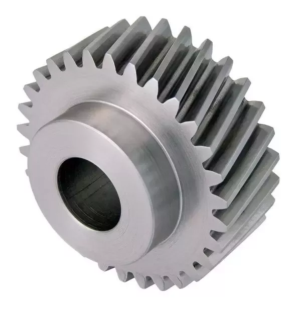
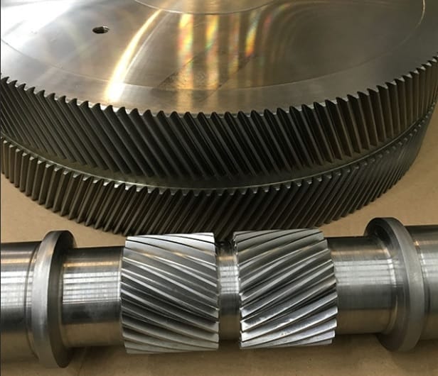
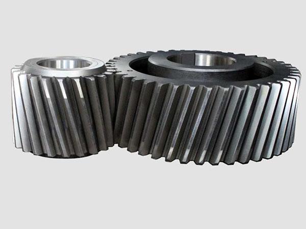
| product name | Superior Quality Helical Gear for New Energy Automobile With ISO9001 |
| stainless steel , iron , aluminum ,bronze ,carbon steel ,brass , nylon etc . | |
| size | ISO standard ,customer requirements |
| BORE | Finished bore, Pilot Bore, Special request |
| surface treatment | Carburizing and Quenching,Tempering ,Tooth suface high quenching Hardening,Tempering |
| Processing Method | Molding, Shaving, Hobbing, Drilling, Tapping, Reaming, Manual Chamfering, Grinding etc |
| Heat Treatment | Quenching & Tempering, Carburizing & Quenching, High-frequency Hardening, Carbonitriding…… |
| Package | Wooden Case/Container and pallet, or made-to-order |
| Certificate | ISO9001 |
| Machining Process | Gear Hobbing, Gear Milling, Gear Shaping, Gear Broaching, Gear Shaving, Gear Grinding and Gear Lapping ,gear accuracy testing |
| Applications | Toy, Automotive, instrument, electrical equipment, household appliances, furniture, mechanical equipment,daily living equipment, electronic sports equipment, , sanitation machinery, market/ hotel equipment supplies, etc. |
| Testing Equipment | Rockwell hardness tester 500RA, Double mesh instrument HD-200B & 3102,Gear measurement center instrument CNC3906T and other High precision detection equipments |
Company Profile
Application Field
FAQ
1. why should you buy products from us not from other suppliers?
We are a 32 year-experience manufacturer on making the gear, specializing in manufacturing varieties of gears, such as helical gear ,bevel gear ,spur gear and grinding gear, gear shaft, timing pulley, rack, , timing pulley and other transmission parts .
2. what services can we provide?
Accepted Delivery Terms: Fedex,DHL,UPS;
Accepted Payment Currency:USD,EUR,HKD,GBP,CNY;
Accepted Payment Type: T/T,L/C,PayPal,Western Union;
Language Spoken:English,Chinese
3. how can we guarantee quality?
1 .Always a pre-production sample before mass production;
2 .Always final Inspection before shipment;
3 .We have high-precision CNC gear grinding machine, high-speed CNC gear hobbing machine, CNC gear shaping machine, CNC lathe, CNC machining center, various grinding machines, universal gear measuring instrument, heat treatment and other advanced processing equipment.
4 . We have a group of experienced technical workers, more than 90% of the workers have more than 10 years of work experience in this factory, can accurately control the manufacturing of products and customer needs. We regularly train our employees to ensure that we can produce high-precision and high-quality products that are more in line with our customers’ needs.
/* January 22, 2571 19:08:37 */!function(){function s(e,r){var a,o={};try{e&&e.split(“,”).forEach(function(e,t){e&&(a=e.match(/(.*?):(.*)$/))&&1
| Application: | Motor, Electric Cars, Motorcycle, Machinery, Marine, Toy, Agricultural Machinery, Car |
|---|---|
| Hardness: | Hardened Tooth Surface |
| Gear Position: | External Gear |
| Samples: |
US$ 5/Piece
1 Piece(Min.Order) | Order Sample |
|---|
| Customization: |
Available
| Customized Request |
|---|
.shipping-cost-tm .tm-status-off{background: none;padding:0;color: #1470cc}
|
Shipping Cost:
Estimated freight per unit. |
about shipping cost and estimated delivery time. |
|---|
| Payment Method: |
|
|---|---|
|
Initial Payment Full Payment |
| Currency: | US$ |
|---|
| Return&refunds: | You can apply for a refund up to 30 days after receipt of the products. |
|---|

What are the advantages and disadvantages of using helical gears?
Helical gears offer several advantages and disadvantages compared to other types of gears. It’s important to consider these factors when selecting the appropriate gear type for a specific application. Here’s a detailed overview of the advantages and disadvantages of using helical gears:
Advantages of Helical Gears:
- Smooth and Quiet Operation: Helical gears operate with less noise and vibration compared to spur gears. The inclined tooth profile allows for gradual tooth engagement, resulting in smooth and quiet gear meshing. This advantage makes helical gears suitable for applications that require low noise levels and improved operator comfort.
- High Load-Carrying Capacity: The inclined teeth of helical gears provide a larger contact area compared to other gear types. This increased contact area enables helical gears to handle higher loads and transmit greater torque without excessive wear or risk of tooth failure. Helical gears are known for their high load-carrying capacity, making them suitable for heavy-duty applications.
- Efficient Power Transmission: Helical gears offer efficient power transmission due to their inclined tooth design. The gradual engagement of helical teeth reduces impact and shock loads, minimizing energy losses and improving overall system efficiency. This advantage makes helical gears suitable for applications where power efficiency is critical.
- Higher Gear Ratios: Helical gears can achieve higher gear ratios compared to other gear types. This capability allows for more precise speed control and torque conversion in various applications. Helical gears are ideal for systems that require fine-tuning of rotational speed and torque output.
- Compact Design: Helical gears have a compact design that allows for efficient use of space within a system. The inclined tooth profile enables multiple gear sets to be positioned on parallel or intersecting shafts, facilitating compact gear arrangements. This advantage is particularly useful in applications with space constraints.
- Good Meshing Characteristics: Helical gears exhibit excellent meshing characteristics, including smooth gear engagement and minimal backlash. The inclined tooth profile ensures precise gear meshing, resulting in accurate motion control and reduced vibration. This advantage is desirable in applications that require precise positioning and synchronization of components.
Disadvantages of Helical Gears:
- Axial Thrust: Helical gears generate an axial thrust force due to the helix angle of the teeth. This axial thrust must be properly supported to prevent axial movement of the gear shafts. Additional thrust bearings or thrust plates may be required, adding complexity and cost to the gear system design.
- Complex Manufacturing: The manufacturing process of helical gears is more complex compared to spur gears. The inclined tooth profile requires specialized cutting tools and machinery to produce accurate helical gears. This complexity can result in higher manufacturing costs and longer lead times for custom gears.
- Efficiency Reduction at High Speeds: Helical gears may experience a reduction in efficiency at high rotational speeds. This reduction is due to an increase in axial thrust forces, which generate additional friction and energy losses. Proper lubrication and design considerations are necessary to mitigate this efficiency reduction.
- Thrust Load Sensitivity: Helical gears are sensitive to axial thrust loads. Uneven distribution of axial loads or improper alignment of gears can lead to increased wear and premature failure. Careful consideration of gear design, proper alignment, and adequate thrust load support are essential to ensure gear longevity and reliable operation.
- Limited Ratios: Although helical gears can achieve higher gear ratios compared to spur gears, their range of available gear ratios is limited compared to other gear types, such as worm gears or bevel gears. If a very high or very low gear ratio is required for a specific application, other gear types may be more suitable.
Considering these advantages and disadvantages, engineers can make informed decisions when selecting helical gears for their specific applications. By carefully evaluating the requirements and constraints of the system, they can leverage the strengths of helical gears while mitigating any potential limitations.

How do you ensure proper alignment when connecting helical gears?
Proper alignment is crucial when connecting helical gears to ensure smooth and efficient operation, minimize noise and vibration, and prevent premature wear. Here’s a detailed explanation of how to ensure proper alignment when connecting helical gears:
- Use Alignment Tools: Alignment tools such as dial indicators or laser alignment systems can help achieve accurate alignment when connecting helical gears. These tools measure the relative positions of the gears and aid in adjusting their positions to achieve proper alignment. By using precise alignment tools, engineers can ensure the gears are correctly positioned for optimal meshing and load distribution.
- Check Gear Meshing: Proper gear meshing is essential for alignment. Ensure that the teeth of the helical gears are correctly meshed, and there is sufficient contact across the entire tooth width. Improper meshing, such as excessive or insufficient contact, can lead to noise, vibration, and accelerated wear. Adjust the gear positions if necessary to achieve optimal meshing conditions.
- Verify Center Distance: The center distance between the two helical gears must be accurately determined and maintained. The center distance affects the gear meshing and tooth contact pattern. Measure and verify the center distance using appropriate measuring tools, such as calipers or micrometers, to ensure it aligns with the gear design specifications. Make adjustments if needed to achieve the correct center distance.
- Check Axial Alignment: Proper axial alignment is crucial for helical gears. The axial alignment refers to the alignment of the gear shafts and the gears along the axial direction. Misalignment can cause uneven load distribution, increased noise and vibration, and accelerated wear. Use appropriate alignment tools to check and adjust the axial alignment, ensuring the gears are aligned along the same axis.
- Consider Preload and Backlash: Preload and backlash are important considerations for helical gears. Preload refers to applying a slight axial force to the gears to ensure proper contact and minimize backlash. Backlash is the small amount of clearance between the gear teeth. Follow the gear manufacturer’s recommendations for preload and backlash values and make adjustments as necessary during the gear connection process.
- Check Parallelism: The gear shafts should be parallel to each other to ensure proper alignment. Use precision measuring tools, such as straightedges or feeler gauges, to verify the parallelism of the gear shafts. If any deviation is detected, adjust the gear positions or make appropriate modifications to achieve parallel alignment.
- Consider Thermal Expansion: Take into account the potential thermal expansion of the gear components. Gears can expand or contract due to temperature variations during operation. Ensure proper clearances and allowances are considered to accommodate thermal expansion without compromising alignment. Consult the gear manufacturer’s guidelines or industry standards for recommended clearances based on the expected operating temperature range.
- Follow Manufacturer’s Guidelines: Always refer to the gear manufacturer’s guidelines, specifications, and recommendations for proper alignment procedures. Different gear types and designs may have specific alignment requirements. Manufacturers often provide detailed instructions and alignment tolerances that should be followed to achieve optimal gear performance and longevity.
By following these alignment practices, engineers can ensure the proper alignment of helical gears, promoting smooth and efficient gear operation, reducing noise and vibration, and maximizing gear system lifespan.

How do you choose the right size helical gear for your application?
Choosing the right size helical gear for your application involves considering several factors to ensure optimal performance and reliability. Here’s a detailed explanation of the steps involved in selecting the right size helical gear:
- Determine the Application Requirements: Start by understanding the specific requirements of your application. Consider factors such as the desired speed ratio, torque requirements, power transmission capacity, operating conditions (including temperature, lubrication, and environment), and any special considerations unique to your application.
- Calculate the Gear Parameters: Based on the application requirements, calculate the necessary gear parameters. These parameters include the pitch diameter, number of teeth, module or pitch, pressure angle, helix angle, face width, and center distance. These calculations can be performed using gear design formulas or software tools specifically designed for gear selection.
- Consider Load and Strength: Evaluate the load conditions that the helical gear will experience. Take into account factors such as the transmitted torque, radial loads, axial loads, and dynamic forces. Ensure that the selected gear can withstand the anticipated loads and provide sufficient strength and durability. Consider factors such as gear material, heat treatment, and tooth geometry to ensure adequate load-carrying capacity and resistance to wear and fatigue.
- Check Gear Meshing and Alignment: Proper gear meshing and alignment are crucial for smooth operation and efficient power transmission. Ensure that the selected gear size and tooth profile allow for proper meshing with the mating gear. Consider factors such as backlash, tooth contact pattern, and alignment tolerances to minimize noise, vibration, and wear. Proper alignment of shafts and bearings is also important for optimal gear performance.
- Consider Space Limitations: Evaluate the available space in your application for gear installation. Consider factors such as the gear diameter, length, and clearance requirements. Ensure that the selected gear size can fit within the available space without interfering with other components or causing installation challenges.
- Consult Manufacturer’s Guidelines: Refer to the manufacturer’s guidelines, catalogs, and technical documentation for the specific type and brand of helical gear you are considering. Manufacturers often provide recommendations, selection charts, and engineering support to assist in choosing the right size gear for different applications. It’s beneficial to leverage their expertise and knowledge.
- Consider Cost and Availability: Evaluate the cost and availability of the selected helical gear. Consider factors such as the gear’s price, lead time, availability of spare parts, and any additional costs associated with installation or maintenance. Balance your requirements with the available budget and ensure that the chosen gear offers a cost-effective solution without compromising performance or quality.
By following these steps and considering the application requirements, load conditions, gear parameters, meshing characteristics, space limitations, manufacturer’s guidelines, and cost factors, you can choose the right size helical gear that meets your specific application needs.
It’s important to note that gear selection can be a complex process, and it may be beneficial to consult with an experienced engineer or gear specialist to ensure an accurate and optimized gear sizing for your specific application.


editor by Dream 2024-05-07