Product Description
Product Description
| Material | Aluminium Alloy,Carbon Steel,Stainless steel,Copper,Brass,Nylon,Plastic(Customized Material) |
| Producing Equipment | 3 Axis,4 Axis,5 Axis CNC Machines,Automatic Lathe Machines,Stamping Machines,CNC Milling machines,CNC Turning Machines,Turning Milling Compound Machines,Grinding Machines,Rolling Machines,Laser Machines. |
| Surface Treatment | Anodizing,Polishing,Electroplating,Heat Treatment,Spray Paint,Sand Blasting. |
| Testing Equipment | Salt Spray Test, Hardness Tester, Coating Thickness Tester, Two Dimensions Measuring Instrument. |
| Quality Testing | 100% Quality Inspection Before Shipment. |
| Lead Time | Generally, The Delivery Date Is 7-15 Days,Delivery Time of Bulk Order Is More Than 15 days. |
| Tolerance and Roughness | Size Tolerance:+/-0.005 – 0.01mm,Roughness: Ra0.2 – Ra3.2 (Custom Size Requirements) |
| Cargo Shipment | Express(DHL,Fedex,UPS, TNT ),Air shipment+Local Express Delivery,Ocean Shipment. |
| Main Markets | America, Europe, Australia, Asia. |
| Payment Type | T/T, L/C, Paypal,Western Union,Others. |
Packaging & Shipping
Company Profile
HangZhou CHINAMFG Technology Co., Ltd. Was established in city known as the “world factory”-HangZhou. We are factory and have many kinds of machine, such as 5-axis CNC machines, lath machines, turning milling compound machines. After 10 years of R&D, production and sales, we have 80% market share in the field of 3D printer parts in China and we are specializing in CNC machinig for 10 years. We are committed to creating a work and production environment that is above the industry average. We adopt scientific production management methods to improve production efficiency and reduce production costs. Please believe and choose us! We adhere to the management principles of “Quality First, Customer first and Credit-based” since the establishment of the company and always do our best to satisfy potential needs of our customers. Our company is sincerely willing to cooperate with enterprises from all over the world in order to realize a CHINAMFG situation since the trend of economic globalization has developed with anirresistible force.
Our Advantages
FAQ
/* January 22, 2571 19:08:37 */!function(){function s(e,r){var a,o={};try{e&&e.split(“,”).forEach(function(e,t){e&&(a=e.match(/(.*?):(.*)$/))&&1
| Application: | Motor, Motorcycle, Machinery, Agricultural Machinery, Car |
|---|---|
| Hardness: | Hardened Tooth Surface |
| Gear Position: | External Gear |
| Toothed Portion Shape: | Spur Gear |
| Material: | Steel |
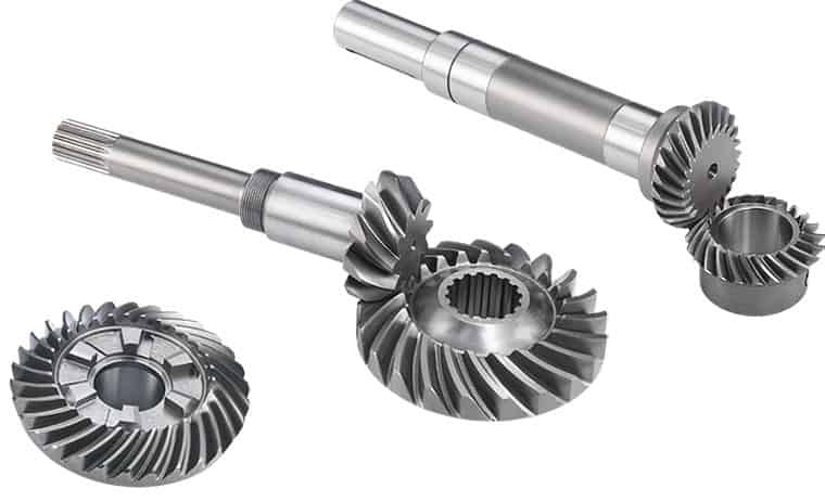
| Type: | Bevel Gear |
| Samples: |
US$ 2/Piece
1 Piece(Min.Order) | |
|---|
| Customization: |
Available
| Customized Request |
|---|
How does a bevel gear impact the overall efficiency of a system?
A bevel gear plays a significant role in determining the overall efficiency of a system. Its design, quality, and operating conditions can impact the efficiency of power transmission and the system as a whole. Here’s a detailed explanation of how a bevel gear can impact overall efficiency:
- Power Transmission Efficiency: The primary function of a bevel gear is to transmit power between intersecting shafts at different angles. The efficiency of power transmission through a bevel gear depends on factors such as gear geometry, tooth profile, material quality, lubrication, and operating conditions. In an ideally designed and well-maintained system, bevel gears can achieve high power transmission efficiency, typically above 95%. However, factors such as friction, misalignment, inadequate lubrication, and gear tooth wear can reduce efficiency and result in power losses.
- Friction and Mechanical Losses: Bevel gears experience friction between their mating teeth during operation. This friction generates heat and causes mechanical losses, reducing the overall efficiency of the system. Factors that affect friction and mechanical losses include the gear tooth profile, surface finish, lubrication quality, and operating conditions. High-quality gears with well-designed tooth profiles, proper lubrication, and optimized operating conditions can minimize friction and mechanical losses, improving the overall efficiency.
- Gear Tooth Design: The design of the bevel gear tooth profile influences its efficiency. Factors such as tooth shape, size, pressure angle, and tooth contact pattern affect the load distribution, friction, and efficiency. Proper tooth design, including optimized tooth profiles and contact patterns, help distribute the load evenly and minimize sliding between the teeth. Well-designed bevel gears with accurate tooth profiles can achieve higher efficiency by reducing friction and wear.
- Material Quality and Manufacturing Precision: The material quality and manufacturing precision of bevel gears impact their durability, smooth operation, and efficiency. High-quality materials with suitable hardness, strength, and wear resistance can minimize friction, wear, and power losses. Additionally, precise manufacturing processes ensure accurate gear geometry, tooth engagement, and alignment, optimizing the efficiency of power transmission and reducing losses due to misalignment or backlash.
- Lubrication and Wear: Proper lubrication is crucial for reducing friction, wear, and power losses in bevel gears. Insufficient or degraded lubrication can lead to metal-to-metal contact, increased friction, and accelerated wear, resulting in reduced efficiency. Adequate lubrication with the recommended lubricant type, viscosity, and replenishment schedule ensures a sufficient lubricating film between the gear teeth, minimizing friction and wear and improving overall efficiency.
- Misalignment and Backlash: Misalignment and excessive backlash in bevel gears can negatively impact efficiency. Misalignment causes uneven loading, increased friction, and accelerated wear. Excessive backlash results in power losses during direction changes and can lead to impact loads and vibration. Proper alignment and control of backlash within acceptable limits are crucial for maintaining high efficiency in a bevel gear system.
Overall, a well-designed bevel gear system with high-quality materials, accurate manufacturing, proper lubrication, and minimal losses due to friction, misalignment, or wear can achieve high efficiency in power transmission. Regular maintenance, monitoring, and optimization of operating conditions are essential to preserve the efficiency of the system over time.
Can bevel gears be used in both horizontal and vertical orientations?
Yes, bevel gears can be used in both horizontal and vertical orientations, although certain considerations should be taken into account for each orientation. Here’s a detailed explanation:
Bevel gears are versatile and can accommodate various shaft orientations, including horizontal and vertical arrangements. The suitability of bevel gears for a specific orientation depends on factors such as load distribution, lubrication, and potential effects of gravity. Here are some considerations for each orientation:
- Horizontal Orientation: In horizontal applications, where the shafts are parallel to the ground, bevel gears can be used effectively. Proper lubrication is crucial to ensure adequate film formation and minimize friction and wear. Horizontal orientation typically allows for good load distribution among the gear teeth, promoting even wear and reducing the risk of localized stress concentrations. However, it is important to consider the effects of axial forces and thrust loads that may be present in the system and ensure that the gear design and bearings can handle these loads appropriately.
- Vertical Orientation: When bevel gears are used in a vertical orientation, where the shafts are perpendicular to the ground, additional considerations come into play. Gravity can introduce new challenges, such as the potential for gear thrust loads, lubricant pooling, and inadequate load distribution. To address these challenges, steps can be taken, including incorporating thrust bearings or thrust plates to handle axial forces, optimizing gear design to ensure proper load sharing, and implementing suitable lubrication methods to prevent lubricant pooling and ensure consistent lubrication to all gear surfaces. Additionally, proper sealing measures may be necessary to prevent lubricant leakage in the vertical orientation.
Overall, by considering the specific requirements and challenges associated with each orientation, bevel gears can be successfully utilized in both horizontal and vertical arrangements. Careful attention to design, lubrication, load distribution, and thrust management can help ensure reliable and efficient operation in either orientation.
It is important to note that for certain extreme or specialized applications, additional considerations and modifications may be required to accommodate the specific demands of the gear system. Consulting with experienced engineers and considering application-specific factors will help determine the most suitable gear design and orientation for a given application.

Are there different types of bevel gears available?
Yes, there are different types of bevel gears available to suit various applications and requirements. Here’s a detailed explanation of the different types of bevel gears:
- Straight Bevel Gears: Straight bevel gears are the most basic type of bevel gears. They have straight-cut teeth that are machined on the cone-shaped surface of the gears. The teeth of straight bevel gears are parallel to the gear axis and intersect at a 90-degree angle. These gears are commonly used when the intersecting shafts need to transmit rotational motion at a right angle.
- Spiral Bevel Gears: Spiral bevel gears are designed with curved teeth that are machined on the cone-shaped surface of the gears. The teeth of spiral bevel gears are cut in a spiral pattern, gradually curving along the gear surface. This spiral tooth geometry provides several advantages over straight bevel gears, including smoother engagement, reduced noise and vibration, and higher load-carrying capacity. Spiral bevel gears are commonly used in applications that require smooth and quiet operation, such as automotive rear axle drives, machine tools, and industrial machinery.
- Hypoid Bevel Gears: Hypoid bevel gears are similar to spiral bevel gears but have offset axes. The axes of hypoid bevel gears do not intersect and are non-parallel, allowing them to transmit rotational motion between shafts that are not in a straight line. Hypoid bevel gears are commonly used in applications where space constraints or specific shaft arrangements require a change in direction and torque transmission. They are often found in automotive drivetrains, power tools, and heavy machinery.
- Straight and Spiral Zerol Bevel Gears: Zerol bevel gears are similar to their straight and spiral counterparts but have a unique tooth profile. The teeth of zerol bevel gears are curved, similar to spiral bevel gears, but with a smaller spiral angle. This results in a tooth profile that is closer to a straight bevel gear. Straight and spiral zerol bevel gears provide a combination of the advantages of both straight and spiral bevel gears, including smoother engagement, reduced noise, and higher load-carrying capacity.
- Straight and Spiral Miter Gears: Miter gears, also known as mitre gears, are a special type of bevel gears that have equal numbers of teeth and intersect at a 90-degree angle. They are often used when rotational motion needs to be transmitted at a right angle without a change in direction. Miter gears can be either straight or spiral, depending on the tooth geometry.
These are the commonly used types of bevel gears. Each type has its own advantages and applications. The selection of the appropriate type of bevel gear depends on factors such as the required angle of transmission, load capacity, noise and vibration considerations, and the specific requirements of the application.
In summary, different types of bevel gears, including straight bevel gears, spiral bevel gears, hypoid bevel gears, straight and spiral zerol bevel gears, and straight and spiral miter gears, are available to suit various applications and accommodate different shaft arrangements.


editor by Dream 2024-05-14
China Standard Hardened Tooth Surface Motor OEM Helical Rack Gears Transmission Hard Spur Gear bevel spiral gear
Product Description
My advantages:
1. High quality materials, professional production, high-precision equipment. Customized design and processing;
2. Strong and durable, strong strength, large torque and good comprehensive mechanical properties;
3. High rotation efficiency, stable and smooth transmission, long service life, noise reduction and shock absorption;
4. Focus on gear processing for 20 years.
5. Carburizing and quenching of tooth surface, strong wear resistance, reliable operation and high bearing capacity;
6. The tooth surface can be ground, and the precision is higher after grinding.
/* January 22, 2571 19:08:37 */!function(){function s(e,r){var a,o={};try{e&&e.split(“,”).forEach(function(e,t){e&&(a=e.match(/(.*?):(.*)$/))&&1
| Application: | Motor, Motorcycle, Machinery, Agricultural Machinery, Car |
|---|---|
| Hardness: | Hardened Tooth Surface |
| Gear Position: | External Gear |
| Manufacturing Method: | Cut Gear |
| Toothed Portion Shape: | Spur Gear |
| Material: | Cast Steel |
| Samples: |
US$ 10/Piece
1 Piece(Min.Order) | |
|---|
| Customization: |
Available
| Customized Request |
|---|

How does a helical gear impact the overall efficiency of a system?
A helical gear has a significant impact on the overall efficiency of a system. Due to their unique design and characteristics, helical gears offer several advantages that contribute to improved efficiency. Here’s a detailed explanation of how a helical gear impacts the overall efficiency of a system:
- Power Transmission: Helical gears provide efficient power transmission due to their inclined tooth design. The helical teeth engage gradually, resulting in a smooth transfer of torque between the gears. This gradual engagement reduces impact and shock loads, minimizing energy losses and improving overall efficiency.
- Load Distribution: The helical tooth profile allows for increased contact area between the gear teeth compared to other gear types. This larger contact area results in improved load distribution across the gear teeth. By distributing the load more evenly, helical gears can handle higher loads without excessive wear and reduce the risk of tooth failure, leading to increased efficiency and reliability.
- Noise and Vibration Reduction: Helical gears operate with less noise and vibration compared to other gear types, such as spur gears. The inclined tooth profile of helical gears helps to minimize gear meshing noise and vibration by distributing the forces along the gear teeth over a larger contact area. Reduced noise and vibration levels contribute to a quieter and smoother operation, indicating lower energy losses and improved overall efficiency.
- Higher Gear Ratios: Helical gears can achieve higher gear ratios compared to other gear types. This capability allows for more precise speed control and torque conversion in various applications. By providing the desired gear ratios, helical gears enable the system to operate at optimal speeds and torque levels, maximizing efficiency and performance.
- Efficient Lubrication: The helical gear design allows for effective lubrication of the gear teeth. The continuous sliding action between the helical teeth assists in distributing the lubricant evenly along the gear contact surfaces. Proper lubrication reduces friction and wear, minimizing energy losses and enhancing the overall efficiency of the gear system.
- Compact Design: Helical gears have a compact design that allows for efficient use of space within a system. The inclined tooth profile enables multiple gear sets to be positioned on parallel or intersecting shafts, facilitating compact gear arrangements. This compactness reduces the overall size and weight of the system while maintaining high efficiency.
- High Precision: Helical gears offer excellent positional accuracy and repeatability. The helical tooth profile ensures precise and consistent gear meshing, resulting in accurate motion control and minimal backlash. This precision contributes to efficient operation, especially in applications requiring precise positioning and synchronization of components.
- Wear Resistance: Helical gears exhibit good wear resistance due to the larger contact area and gradual tooth engagement. The inclined tooth profile helps distribute the load, reducing localized wear and extending the gear’s service life. Reduced wear translates to sustained gear efficiency over time, minimizing the need for frequent replacements and maintenance.
Overall, the design characteristics of helical gears, including smooth power transmission, load distribution, noise reduction, higher gear ratios, efficient lubrication, compactness, precision, and wear resistance, collectively contribute to improved system efficiency. By choosing helical gears appropriately for a given application, engineers can enhance the overall performance, reliability, and energy efficiency of the system.

How do you calculate the efficiency of a helical gear?
The efficiency of a helical gear can be calculated by comparing the power input to the gear with the power output. The efficiency represents the ratio of the output power to the input power, expressed as a percentage. Here’s a detailed explanation of how to calculate the efficiency of a helical gear:
The formula for calculating gear efficiency is:
Efficiency = (Power Output / Power Input) * 100%
To calculate the efficiency, you need to determine the power input and power output values. Here are the steps involved:
- Power Input: The power input to the gear is the amount of power supplied to the gear system. It can be determined by multiplying the input torque (Tin) by the input rotational speed (Nin) in radians per second. The formula for power input is:
Power Input = Tin * Nin
- Power Output: The power output from the gear is the amount of power delivered by the gear system. It can be calculated by multiplying the output torque (Tout) by the output rotational speed (Nout) in radians per second. The formula for power output is:
Power Output = Tout * Nout
- Calculate Efficiency: Once you have determined the power input and power output values, you can calculate the gear efficiency using the formula mentioned earlier:
Efficiency = (Power Output / Power Input) * 100%
The resulting efficiency value will be a percentage, representing the proportion of input power that is effectively transmitted as output power by the helical gear system. A higher efficiency value indicates a more efficient gear system, with less power loss during the gear transmission.
It’s important to note that gear efficiency can be influenced by various factors, including gear design, tooth profile, operating conditions, lubrication, and manufacturing quality. Therefore, the calculated efficiency represents an estimate based on the given input and output power values, and it may vary in real-world applications.
What are the applications of helical gears?
Helical gears find wide-ranging applications in various mechanical systems due to their advantageous characteristics and capabilities. Here’s a detailed explanation of the applications of helical gears:
1. Power Transmission: Helical gears are commonly used for power transmission in a wide range of industries. They are employed in machinery and equipment where rotational motion needs to be transmitted between parallel shafts. Examples include gearboxes, industrial machinery, conveyors, and automotive transmissions.
2. Rotary Motion Control: Helical gears are used in applications where precise rotary motion control is required. They provide smooth and accurate motion transfer, making them suitable for applications such as robotics, precision equipment, machine tools, and positioning systems.
3. High Torque Applications: Due to their design and tooth engagement characteristics, helical gears are well-suited for high torque applications. They can efficiently transmit substantial power and handle heavy loads. This makes them suitable for heavy machinery, construction equipment, mining machinery, and marine propulsion systems.
4. Automotive Industry: Helical gears are extensively used in automotive applications. They are found in transmissions, differentials, and powertrain systems, where they facilitate smooth and efficient power transmission while reducing noise and vibration. Helical gears help achieve the desired gear ratios and torque multiplication in vehicles.
5. Machine Tools: Machine tools, such as milling machines, lathes, and gear hobbing machines, utilize helical gears for precise motion control and power transmission. Helical gears enable accurate and smooth rotation of cutting tools and workpieces, contributing to the high precision and quality of machined components.
6. Printing Industry: Helical gears are used in printing presses and other printing equipment. They facilitate the precise movement of paper and printing plates, ensuring accurate registration and high-quality printing results.
7. Textile Industry: In the textile industry, helical gears are employed in various machinery and equipment. They are used in spinning machines, weaving machines, and other textile processing equipment that require precise motion control and power transmission for efficient textile production.
8. Oil and Gas Industry: Helical gears are utilized in oil and gas equipment and machinery. They are found in pumps, compressors, drilling rigs, and other critical components where high torque transmission and reliable motion control are essential for efficient operations.
9. Power Generation: Helical gears play a crucial role in power generation systems. They are employed in wind turbines, hydroelectric generators, and other power generation equipment to transmit rotational motion from the turbine or generator shaft to the electrical generator, ensuring efficient electricity production.
10. General Machinery: Helical gears have diverse applications in general machinery across various industries. They are used in packaging equipment, food processing machinery, material handling systems, and numerous other mechanical systems that require reliable power transmission and precise motion control.
The versatility, load-carrying capacity, and smooth operation of helical gears make them suitable for numerous applications in different industries. The specific design, tooth profile, helix angle, and material selection can be tailored to meet the requirements of each application, ensuring optimal performance and longevity of the gear system.
editor by Dream 2024-05-14
China best High Efficiency Helical Gear for Automotive Rear Axle Gearbox and Robotic with ISO9001 with Good quality
Product Description
Product Parameters
| product name | High Efficiency Helical Gear for Automotive Rear Axle Gearbox And Robotic With ISO9001 |
| material | stainless steel , iron , aluminum ,bronze ,carbon steel ,brass , nylon etc . |
| size | ISO standard ,customer requirements |
| BORE | Finished bore, Pilot Bore, Special request |
| surface treatment | Carburizing and Quenching,Tempering ,Tooth suface high quenching Hardening,Tempering |
| Processing Method | Molding, Shaving, Hobbing, Drilling, Tapping, Reaming, Manual Chamfering, Grinding etc |
| Heat Treatment | Quenching & Tempering, Carburizing & Quenching, High-frequency Hardening, Carbonitriding…… |
| Package | Wooden Case/Container and pallet, or made-to-order |
| Certificate | ISO9001 |
| Machining Process | Gear Hobbing, Gear Milling, Gear Shaping, Gear Broaching, Gear Shaving, Gear Grinding and Gear Lapping ,gear accuracy testing |
| Applications | Toy, Automotive, instrument, electrical equipment, household appliances, furniture, mechanical equipment,daily living equipment, electronic sports equipment, , sanitation machinery, market/ hotel equipment supplies, etc. |
| Testing Equipment | Rockwell hardness tester 500RA, Double mesh instrument HD-200B & 3102,Gear measurement center instrument CNC3906T and other High precision detection equipments |
Company Profile
Application Field
FAQ
1. why should you buy products from us not from other suppliers?
We are a 32 year-experience manufacturer on making the gear, specializing in manufacturing varieties of gears, such as helical gear ,bevel gear ,spur gear and grinding gear, gear shaft, timing pulley, rack, , timing pulley and other transmission parts .
2. what services can we provide?
Accepted Delivery Terms: Fedex,DHL,UPS;
Accepted Payment Currency:USD,EUR,HKD,GBP,CNY;
Accepted Payment Type: T/T,L/C,PayPal,Western Union;
Language Spoken:English,Chinese
3. how can we guarantee quality?
1 .Always a pre-production sample before mass production;
2 .Always final Inspection before shipment;
3 .We have high-precision CNC gear grinding machine, high-speed CNC gear hobbing machine, CNC gear shaping machine, CNC lathe, CNC machining center, various grinding machines, universal gear measuring instrument, heat treatment and other advanced processing equipment.
4 . We have a group of experienced technical workers, more than 90% of the workers have more than 10 years of work experience in this factory, can accurately control the manufacturing of products and customer needs. We regularly train our employees to ensure that we can produce high-precision and high-quality products that are more in line with our customers’ needs.
/* January 22, 2571 19:08:37 */!function(){function s(e,r){var a,o={};try{e&&e.split(“,”).forEach(function(e,t){e&&(a=e.match(/(.*?):(.*)$/))&&1
| Application: | Motor, Electric Cars, Motorcycle, Machinery, Marine, Toy, Agricultural Machinery, Car |
|---|---|
| Hardness: | Hardened Tooth Surface |
| Gear Position: | External Gear |
| Manufacturing Method: | Cut Gear |
| Toothed Portion Shape: | Spur Gear |
| Material: | Stainless Steel |
| Samples: |
US$ 5/Piece
1 Piece(Min.Order) | |
|---|
| Customization: |
Available
| Customized Request |
|---|
How do you maintain and service a helical gear system?
Maintaining and servicing a helical gear system is essential to ensure its long-term performance, reliability, and longevity. Proper maintenance practices help identify and address potential issues before they lead to gear failure or reduced efficiency. Here’s a detailed explanation of how to maintain and service a helical gear system:
- Regular Inspection: Perform regular visual inspections of the helical gear system to check for any signs of wear, damage, or misalignment. Inspect the gear teeth, shafts, bearings, and lubrication system for any abnormalities. Look for indications such as pitting, chipping, excessive tooth wear, or unusual noise or vibration during operation.
- Lubrication Maintenance: Ensure proper lubrication of the helical gears as per the manufacturer’s recommendations. Monitor lubricant levels, quality, and contamination. Periodically check and replenish or replace the lubricant as necessary. Follow the recommended lubrication intervals and use the appropriate lubricant type and viscosity for the operating conditions.
- Gear Cleaning: Keep the gear system clean and free from debris or contaminants. Regularly remove any accumulated dirt, dust, or foreign particles that may affect the gear performance. Use appropriate cleaning methods such as brushing, wiping, or compressed air to maintain a clean gear environment.
- Alignment Check: Misalignment can lead to premature gear failure and reduced efficiency. Periodically check the shaft alignment using precision alignment tools. Ensure that the shafts are properly aligned both radially and axially. If misalignment is detected, take corrective measures such as adjusting the shaft positions or using shims to reestablish proper alignment.
- Check Gear Meshing: Monitor the gear meshing to ensure proper tooth engagement and contact. Regularly inspect the tooth contact pattern to identify any irregularities or changes. If necessary, make adjustments to the gear position or shim thickness to achieve the desired tooth contact pattern and optimize gear performance.
- Bearing Maintenance: Check the condition of the bearings supporting the helical gears. Monitor for any signs of wear, damage, or inadequate lubrication. Replace worn-out or faulty bearings promptly to prevent further damage to the gear system. Follow the manufacturer’s guidelines for bearing maintenance, lubrication, and replacement.
- Vibration Analysis: Perform periodic vibration analysis to detect any abnormal vibration patterns that may indicate gear or bearing problems. Use vibration monitoring tools and techniques to identify the source and severity of the vibrations. If excessive vibrations are detected, investigate and rectify the underlying causes to prevent gear damage or failure.
- Temperature Monitoring: Monitor the temperature of the helical gear system during operation. Excessive heat can be an indication of inadequate lubrication, overloading, or other issues. Regularly measure and record the gear system’s operating temperature to identify any abnormal temperature rise and take appropriate action if necessary.
- Training and Documentation: Ensure that maintenance personnel are properly trained in helical gear system maintenance and servicing. Maintain detailed documentation of maintenance activities, including inspection records, lubrication schedules, and any repairs or replacements performed. This documentation helps track the gear system’s history and assists in troubleshooting and future maintenance planning.
- Consult with Experts: When in doubt or when dealing with complex gear systems, consult with gear manufacturers, industry experts, or experienced engineers for guidance on specific maintenance procedures or troubleshooting techniques. They can provide valuable insights and recommendations based on their expertise and experience.
By following these maintenance and servicing practices, you can ensure the optimal performance, reliability, and longevity of your helical gear system. Regular inspections, proper lubrication, alignment checks, and timely repairs or replacements are crucial for minimizing downtime, extending gear life, and maximizing the efficiency of the gear system.

What are the potential challenges in designing and manufacturing helical gears?
Designing and manufacturing helical gears can present various challenges that need to be addressed to ensure optimal performance and durability. Here’s a detailed explanation of the potential challenges encountered in designing and manufacturing helical gears:
- Complex Geometry: The geometry of helical gears is more complex compared to other gear types. The helical tooth profile requires precise calculations and manufacturing techniques to achieve the desired gear performance. Designers must account for factors such as helix angle, lead angle, tooth shape modification, and tooth contact pattern optimization. The complex geometry adds challenges to both the design and manufacturing processes.
- Manufacturing Accuracy: Achieving the required manufacturing accuracy for helical gears can be challenging. The gear teeth must have precise profiles and dimensions to ensure proper meshing and load distribution. The manufacturing processes, such as gear cutting (e.g., hobbing or grinding), must be carefully controlled to achieve the desired tooth geometry, surface finish, and dimensional accuracy. Maintaining tight tolerances and minimizing manufacturing variations are crucial to ensure the gears meet the design specifications.
- Axial Thrust and Bearing Considerations: Helical gears generate axial thrust forces due to the helix angle. The axial thrust can affect gear performance and may require additional measures to properly manage. Adequate bearing selection and support systems must be designed to accommodate the axial loads and ensure smooth gear operation. Consideration should also be given to the potential thrust-induced axial movement and its impact on gear alignment and system performance.
- Noise and Vibration: Helical gears can produce noise and vibration during operation, particularly if not designed or manufactured correctly. Factors such as improper tooth contact, misalignment, or excessive gear backlash can contribute to increased noise and vibration levels. Designers and manufacturers must carefully analyze and optimize the gear geometry, tooth contact patterns, and manufacturing processes to minimize noise and vibration and ensure quieter operation.
- Lubrication Challenges: Proper lubrication is critical for the smooth operation and longevity of helical gears. However, the helical tooth profile can pose challenges for lubricant distribution. The inclined teeth create a sliding action that may affect lubricant film formation and retention. Ensuring adequate lubrication to all gear surfaces, including the tooth flanks and root fillets, becomes important. Designing efficient lubrication systems and selecting appropriate lubricants that can withstand the sliding action and provide sufficient film thickness is crucial.
- Heat Dissipation: Helical gears can generate significant heat during operation, especially at high speeds or under heavy loads. Effective heat dissipation is essential to prevent overheating and premature wear. Designers and manufacturers need to consider heat dissipation mechanisms, such as proper housing design, cooling methods, and suitable materials with good thermal conductivity. Adequate ventilation and lubrication systems should also be designed to facilitate heat dissipation and maintain optimum operating temperatures.
- Tooling and Equipment: Manufacturing helical gears often requires specialized tooling and equipment. The gear cutting processes, such as hobbing or grinding, may necessitate specific tools, cutters, or grinding wheels. These tools must be properly selected, calibrated, and maintained to achieve accurate tooth profiles and finishes. The availability of suitable tooling and equipment, as well as the expertise to operate and maintain them, can be a challenge for gear manufacturers.
- Cost Considerations: Designing and manufacturing helical gears can involve higher costs compared to simpler gear types. The complexity of gear geometry, precision manufacturing requirements, specialized tooling, and additional considerations such as bearing support or noise reduction measures can contribute to increased production costs. Balancing the desired gear performance with cost considerations can be challenging for designers and manufacturers.
By addressing these potential challenges through careful design, precise manufacturing processes, and proper selection of materials and lubrication, engineers can overcome the complexities associated with designing and manufacturing helical gears and ensure high-quality gears that meet performance requirements and deliver long-term reliability.

Are there different types of helical gears available?
Yes, there are different types of helical gears available to meet specific application requirements. Here’s a detailed explanation of some common types of helical gears:
- Parallel Helical Gears: Parallel helical gears are the most commonly used type of helical gears. In this configuration, two helical gears with parallel axes are meshed together. They transmit power and motion between parallel shafts. Parallel helical gears provide smooth operation, high load-carrying capacity, and efficient power transmission.
- Double Helical Gears (Herringbone Gears): Double helical gears, also known as herringbone gears, have two sets of helical teeth that are placed in a V-shaped configuration. The V-shaped teeth face each other, with a groove or gap in the middle. This design cancels out the axial thrust that is generated by the helical gear’s inclined teeth. Double helical gears are often used in applications that require high torque transmission and axial load balancing, such as heavy machinery and marine propulsion systems.
- Crossed Helical Gears (Screw Gears): Crossed helical gears, also referred to as screw gears, involve the meshing of two helical gears with non-parallel and non-intersecting axes. The gears are oriented at an angle to each other, typically 90 degrees. Crossed helical gears are used in applications where shafts intersect or when a compact and non-parallel gear arrangement is required. They are commonly found in hand drills, speedometers, and some mechanical watches.
- Skew Gears: Skew gears are a type of helical gear in which the gear teeth are cut at an angle to the gear axis. The angle of the teeth can vary, allowing for different degrees of skew. Skew gears are used in applications where the axes of the mating gears are neither parallel nor intersecting. They can transmit power between non-parallel and non-intersecting shafts while accommodating misalignments.
- Helical Rack and Pinion: A helical rack and pinion system consists of a helical gear (pinion) that meshes with a linear gear (rack). The pinion is a cylindrical gear with helical teeth, while the rack is a straight bar with teeth that mesh with the pinion. This configuration is commonly used in applications that require linear motion, such as CNC machines, robotics, and rack and pinion steering systems in automobiles.
- Variable Helix Gears: Variable helix gears have a unique tooth profile where the helix angle varies along the face width of the gear. The varying helix angle helps to reduce noise, vibration, and backlash while maintaining smooth operation and load distribution. These gears are often used in high-performance applications where noise reduction and precise motion control are critical.
The specific type of helical gear used depends on factors such as the application requirements, load conditions, space limitations, and desired performance characteristics. Manufacturers often provide various options and customizations to meet specific needs.
It’s important to note that the design and manufacturing of helical gears require careful consideration of factors such as tooth profile, helix angle, lead angle, module or pitch, pressure angle, and material selection. These factors ensure proper gear meshing, load distribution, and efficient power transmission.
In summary, different types of helical gears, including parallel helical gears, double helical gears (herringbone gears), crossed helical gears (screw gears), skew gears, helical rack and pinion systems, and variable helix gears, are available to cater to a wide range of applications. Each type has its unique characteristics and advantages, allowing for optimized performance and reliable power transmission in various industries and machinery.
editor by Dream 2024-05-14
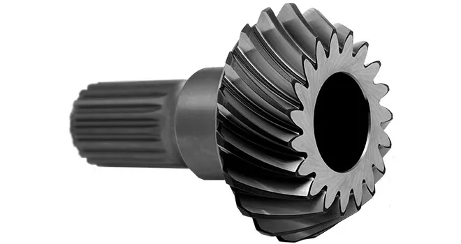
China best Gear Shaft Dia 260mm Module3.5 Teeth 62 Bevel Gear Spur Gear Internal Gear for Big Machine Reducer gear ratio calculator
Product Description
Product introduction
| Gear model | Customized gear shaft accoding to customers sample or drawing |
| Processing machine | CNC machine |
| Material | 20CrMnTi/ 20CrMnMo/ 42CrMo/ 45#steel/ 40Cr/ 20CrNi2MoA |
| Heat treattment | Carburizing and quenching/ Tempering/ Nitriding/ Carbonitriding/ Induction hardening |
| Hardness | 58-62HRC |
| Qaulity standerd | GB/ DIN/ JIS/ AGMA |
| Accuracy class | 5-8 class |
| Shipping | Sea shipping/ Air shipping/ Express |
Factory introduction
ZheJiang Yingxing Gear Co., LTD is set product development, production and sales of specialized enterprises, the company was founded in 2007, is located in Xihu (West Lake) Dis. Bridge River, 50 kilometers from the provincial capital HangZhou city, convenient transportation.
The company has modern professional production workshop covers an area of 30,000 square meters, 120 employees, including professional and technical staff of 30 people. We buy the advanced processing center equipment from Germany and American. We produce the gear for reducer,agricultural machinery, construction machinery, oil drilling rig,and other aspects of the production. The company has been appraised as ZheJiang quality products, corporate credit quality units. The company has offices in HangZhou.
Our products sell well in China and exported to Europe, the Americas, the Middle East, Southeast Asia and other countries. My company adhered to the “good faith, winning by quality, first-class service will be presented to our customers” for the purpose, we are willing to be honest with you, and work together for a better tomorrow.
Factory pictures and cerfitication
/* January 22, 2571 19:08:37 */!function(){function s(e,r){var a,o={};try{e&&e.split(“,”).forEach(function(e,t){e&&(a=e.match(/(.*?):(.*)$/))&&1
| Standard: | China GB Code |
|---|---|
| Surface Treatment: | Heat Treament |
| Production Type: | Single Production |
| Machining Method: | CNC Machining |
| Material: | 42CrMo |
| Gear Model: | Customized Gear |
| Customization: |
Available
| Customized Request |
|---|

What are the advantages and disadvantages of using a bevel gear?
Bevel gears offer several advantages and disadvantages when used in mechanical systems. Understanding these pros and cons is crucial for selecting the appropriate gear type for a given application. Here’s a detailed explanation of the advantages and disadvantages of using a bevel gear:
Advantages of Bevel Gears:
- Power Transmission at Different Angles: Bevel gears are specifically designed to transmit power between intersecting shafts at different angles. They allow for efficient torque transmission and direction changes in applications where the input and output shafts are not parallel. This flexibility makes bevel gears suitable for a wide range of mechanical systems.
- Compact Design: Bevel gears have a compact and space-efficient design, allowing them to be used in applications with limited space constraints. Their ability to transmit power at an angle helps in optimizing the layout and arrangement of components in machinery and equipment.
- High Efficiency: Well-designed and properly maintained bevel gears can achieve high power transmission efficiency, typically above 95%. The efficient tooth engagement and load distribution in bevel gears minimize power losses due to friction and mechanical inefficiencies, resulting in energy-efficient operation.
- Smooth and Quiet Operation: Bevel gears generally provide smooth and quiet operation in properly designed and well-maintained systems. The meshing of the gear teeth is designed to minimize noise and vibration, ensuring smooth power transmission and reducing the need for additional noise-reducing measures.
- Versatility: Bevel gears are available in various configurations, including straight bevel, spiral bevel, and hypoid bevel gears. This versatility allows them to be used in a wide range of applications across different industries, accommodating different load capacities, speed requirements, and operating conditions.
- High Load Capacity: Bevel gears are capable of handling high loads and transmitting substantial amounts of torque. Their robust design, accurate tooth engagement, and strong materials make them suitable for heavy-duty applications where reliable power transmission is required.
Disadvantages of Bevel Gears:
- Complex Manufacturing: Bevel gears are more complex to manufacture compared to other gear types due to their three-dimensional shape and intricate tooth profiles. The manufacturing process involves specialized equipment and expertise, which can increase production costs.
- Cost: Bevel gears, especially those with high precision and load capacities, can be relatively expensive compared to other types of gears. The cost of materials, manufacturing complexity, and quality requirements contribute to their higher price.
- Potential for Noise and Vibration: In certain operating conditions, such as high speeds or misaligned gears, bevel gears can generate noise and vibration. This can be mitigated through proper design, accurate manufacturing, and maintenance practices, but additional measures may be necessary to reduce noise and vibration levels in some applications.
- Sensitive to Misalignment: Bevel gears are sensitive to misalignment, which can lead to increased friction, accelerated wear, and reduced efficiency. Proper alignment and control of backlash are essential for optimal performance and longevity of the gear system.
- Complex Lubrication: The lubrication of bevel gears can be more challenging compared to parallel-axis gears. Due to their angled tooth engagement, ensuring proper lubrication film thickness and distribution across the gear teeth requires careful consideration. Inadequate or improper lubrication can result in increased friction, wear, and reduced efficiency.
It’s important to consider these advantages and disadvantages of bevel gears in the context of specific applications and operating conditions. Proper design, selection, manufacturing, and maintenance practices can help maximize the benefits of bevel gears while mitigating their limitations.

What are the potential challenges in designing and manufacturing bevel gears?
Designing and manufacturing bevel gears can present several challenges due to their complex geometry, load requirements, and manufacturing processes. Here’s a detailed explanation of the potential challenges:
When it comes to designing and manufacturing bevel gears, the following challenges may arise:
- Complex Geometry: Bevel gears have intricate geometry with non-parallel and intersecting tooth profiles. Designing bevel gears requires a thorough understanding of gear theory, tooth engagement, and load distribution. The complex geometry poses challenges in determining the optimal tooth profile, tooth contact pattern, and gear ratios for the specific application.
- Load Analysis and Distribution: Determining the correct load analysis and distribution is crucial to ensure the gears can handle the anticipated forces and torques. Bevel gears often encounter varying loads, including radial loads, axial loads, and bending moments. Accurately predicting and distributing these loads across the gear teeth is essential for achieving proper gear strength, minimizing wear, and preventing premature failure.
- Manufacturing Precision: Bevel gears require high manufacturing precision to ensure smooth operation, minimal backlash, and efficient power transmission. Achieving the required precision in gear manufacturing involves precise machining, grinding, and heat treatment processes. The complex geometry of bevel gears adds to the manufacturing complexity, necessitating specialized equipment and skilled operators.
- Alignment Challenges: Proper alignment of bevel gears is critical for optimal performance and longevity. Achieving accurate alignment can be challenging due to the non-parallel shafts and intricate tooth profiles. Misalignment can lead to increased noise, vibration, and premature wear. Design considerations for alignment, as well as careful assembly and alignment procedures during manufacturing, are necessary to address this challenge.
- Lubrication and Cooling: Bevel gears require effective lubrication to minimize friction, wear, and heat generation. Ensuring proper lubrication and cooling can be challenging due to the unique shape of bevel gears and the limited space available for lubricant circulation. Designing appropriate lubrication systems, selecting suitable lubricants, and considering heat dissipation methods are essential for maintaining optimal gear performance and preventing overheating.
- Quality Control: Maintaining consistent quality during the manufacturing process is crucial for reliable bevel gears. Implementing robust quality control measures, including dimensional inspections, surface quality assessments, and gear testing, helps ensure that the manufactured gears meet the specified requirements. Consistency in gear quality is essential to minimize variations in performance and to ensure accurate gear meshing and load distribution.
Addressing these challenges requires a combination of engineering expertise, advanced manufacturing techniques, and quality control processes. Collaborating with experienced gear designers, employing state-of-the-art manufacturing technologies, and conducting thorough testing and analysis can help overcome these challenges and produce high-quality bevel gears that meet the performance and durability requirements of the intended application.

How do you calculate the gear ratio of a bevel gear?
Calculating the gear ratio of a bevel gear involves determining the ratio between the number of teeth on the driving gear (pinion) and the driven gear (crown gear). Here’s a detailed explanation of how to calculate the gear ratio of a bevel gear:
The gear ratio is determined by the relationship between the number of teeth on the pinion and the crown gear. The gear ratio is defined as the ratio of the number of teeth on the driven gear (crown gear) to the number of teeth on the driving gear (pinion). It can be calculated using the following formula:
Gear Ratio = Number of Teeth on Crown Gear / Number of Teeth on Pinion Gear
For example, let’s consider a bevel gear system with a crown gear that has 40 teeth and a pinion gear with 10 teeth. The gear ratio can be calculated as follows:
Gear Ratio = 40 / 10 = 4
In this example, the gear ratio is 4:1, which means that for every four revolutions of the driving gear (pinion), the driven gear (crown gear) completes one revolution.
It’s important to note that the gear ratio can also be expressed as a decimal or a percentage. For the example above, the gear ratio can be expressed as 4 or 400%.
Calculating the gear ratio is essential for understanding the speed relationship and torque transmission between the driving and driven gears in a bevel gear system. The gear ratio determines the relative rotational speed and torque amplification or reduction between the gears.
It’s worth mentioning that the gear ratio calculation assumes ideal geometries and does not consider factors such as backlash, efficiency losses, or any other system-specific considerations. In practical applications, it’s advisable to consider these factors and consult gear manufacturers or engineers for more accurate calculations and gear selection.
In summary, the gear ratio of a bevel gear is determined by dividing the number of teeth on the crown gear by the number of teeth on the pinion gear. The gear ratio defines the speed and torque relationship between the driving and driven gears in a bevel gear system.
editor by Dream 2024-05-14
China factory CNC Machining Forged Steel Big Helical Pinion Gear Custom High Quality Drive Large Gear with high quality
Product Description
CNC machining forged steel big helical pinion gear custom high quality drive large gear
Product Parameters
| product name | CNC machining forged steel big helical pinion gear custom high quality drive large gear |
| material | stainless steel , iron , aluminum ,bronze ,carbon steel ,brass , nylon etc . |
| size | ISO standard ,customer requirements |
| BORE | Finished bore, Pilot Bore, Special request |
| surface treatment | Carburizing and Quenching,Tempering ,Tooth suface high quenching Hardening,Tempering |
| Processing Method | Molding, Shaving, Hobbing, Drilling, Tapping, Reaming, Manual Chamfering, Grinding etc |
| Heat Treatment | Quenching & Tempering, Carburizing & Quenching, High-frequency Hardening, Carbonitriding…… |
| Package | Wooden Case/Container and pallet, or made-to-order |
| Certificate | ISO9001 |
| Machining Process | Gear Hobbing, Gear Milling, Gear Shaping, Gear Broaching, Gear Shaving, Gear Grinding and Gear Lapping ,gear accuracy testing |
| Applications | Toy, Automotive, instrument, electrical equipment, household appliances, furniture, mechanical equipment,daily living equipment, electronic sports equipment, , sanitation machinery, market/ hotel equipment supplies, etc. |
| Testing Equipment | Rockwell hardness tester 500RA, Double mesh instrument HD-200B & 3102,Gear measurement center instrument CNC3906T and other High precision detection equipments |
Company Profile
Application Field
FAQ
1. why should you buy products from us not from other suppliers?
We are a 32 year-experience manufacturer on making the gear, specializing in manufacturing varieties of gears, such as helical gear ,bevel gear ,spur gear and grinding gear, gear shaft, timing pulley, rack, , timing pulley and other transmission parts .
2. what services can we provide?
Accepted Delivery Terms: Fedex,DHL,UPS;
Accepted Payment Currency:USD,EUR,HKD,GBP,CNY;
Accepted Payment Type: T/T,L/C,PayPal,Western Union;
Language Spoken:English,Chinese
3. how can we guarantee quality?
1 .Always a pre-production sample before mass production;
2 .Always final Inspection before shipment;
3 .We have high-precision CNC gear grinding machine, high-speed CNC gear hobbing machine, CNC gear shaping machine, CNC lathe, CNC machining center, various grinding machines, universal gear measuring instrument, heat treatment and other advanced processing equipment.
4 . We have a group of experienced technical workers, more than 90% of the workers have more than 10 years of work experience in this factory, can accurately control the manufacturing of products and customer needs. We regularly train our employees to ensure that we can produce high-precision and high-quality products that are more in line with our customers’ needs.
/* January 22, 2571 19:08:37 */!function(){function s(e,r){var a,o={};try{e&&e.split(“,”).forEach(function(e,t){e&&(a=e.match(/(.*?):(.*)$/))&&1
| Application: | Motor, Electric Cars, Motorcycle, Machinery, Marine, Toy, Agricultural Machinery, Car, Packing Machine |
|---|---|
| Hardness: | Hardened Tooth Surface |
| Gear Position: | External Gear |
| Customization: |
Available
| Customized Request |
|---|
.shipping-cost-tm .tm-status-off{background: none;padding:0;color: #1470cc}
|
Shipping Cost:
Estimated freight per unit. |
about shipping cost and estimated delivery time. |
|---|
| Payment Method: |
|
|---|---|
|
Initial Payment Full Payment |
| Currency: | US$ |
|---|
| Return&refunds: | You can apply for a refund up to 30 days after receipt of the products. |
|---|
Are helical gears suitable for high-torque applications?
Helical gears are indeed well-suited for high-torque applications. Their design features and characteristics make them capable of handling significant torque loads without compromising performance or durability. Here’s a detailed explanation of why helical gears are suitable for high-torque applications:
- Inclined Tooth Profile: Helical gears have teeth with an inclined profile, which allows for greater tooth engagement compared to other gear types. This increased contact area spreads the load over multiple teeth, distributing the torque more evenly. As a result, helical gears can handle higher torque levels without exceeding the strength limits of the gear teeth.
- Large Contact Ratio: The inclined tooth design of helical gears also contributes to a large contact ratio, which refers to the number of teeth in contact at any given moment. The large contact ratio enables helical gears to transmit torque more smoothly and efficiently. It reduces localized stress on individual teeth, minimizing the risk of tooth failure and enhancing the gear’s ability to handle high-torque loads.
- High Load-Carrying Capacity: Helical gears are known for their high load-carrying capacity. The inclined tooth profile and larger contact area allow helical gears to distribute the torque load over a broader surface, reducing the stress on individual teeth. This design feature enables helical gears to handle higher torque levels without experiencing premature wear or failure.
- Gradual Tooth Engagement: During gear meshing, the inclined teeth of helical gears gradually engage, resulting in a smooth and gradual transfer of torque. This gradual engagement helps to reduce impact and shock loads, which can be detrimental to gear performance. By minimizing sudden torque spikes, helical gears maintain a consistent and reliable torque transmission, making them suitable for high-torque applications.
- Efficient Power Transmission: Helical gears offer efficient power transmission, even in high-torque applications. The inclined tooth design reduces sliding friction between the gear teeth, resulting in lower energy losses and improved overall efficiency. This efficiency is particularly beneficial in high-torque applications where power consumption and heat generation need to be minimized.
- Ability to Handle Variable Torque: Helical gears are capable of handling variable torque loads effectively. The gradual tooth engagement and larger contact area allow helical gears to accommodate fluctuations in torque without compromising performance. This flexibility makes helical gears suitable for applications where torque requirements may vary during operation.
In summary, helical gears are well-suited for high-torque applications due to their inclined tooth profile, large contact ratio, high load-carrying capacity, gradual tooth engagement, efficient power transmission, and ability to handle variable torque. These characteristics make helical gears reliable and durable in demanding industrial scenarios where high torque levels are encountered.
How do you address noise and vibration issues in a helical gear system?
In a helical gear system, addressing noise and vibration issues is crucial to ensure smooth and quiet operation, minimize component wear, and enhance overall system performance. Here’s a detailed explanation of how to address noise and vibration issues in a helical gear system:
- Proper Gear Design: The design of the helical gears can significantly impact noise and vibration levels. Design considerations such as the helix angle, tooth profile modification, and gear tooth contact pattern optimization can help minimize gear noise and vibration. A well-designed gear system with proper tooth geometry and accurate alignment reduces the likelihood of gear meshing irregularities that contribute to noise and vibration.
- Precision Manufacturing: High-quality manufacturing processes are essential to minimize noise and vibration in helical gear systems. Precise gear cutting techniques, such as hobbing or grinding, ensure accurate tooth profiles, which help reduce gear meshing deviations and associated noise. Additionally, maintaining tight manufacturing tolerances and surface finishes on gear components can help minimize vibration caused by irregularities or imperfections.
- Alignment and Assembly: Proper alignment and assembly of the helical gears are critical to minimize noise and vibration. Ensuring precise alignment of the gear shafts and gear meshing is essential to achieve optimal contact between the gear teeth. The use of alignment tools, such as dial indicators or laser alignment systems, can aid in achieving accurate alignment. Additionally, proper assembly techniques, including appropriate gear backlash and preload adjustment, can help minimize noise and vibration by optimizing gear meshing conditions.
- Optimal Lubrication: Proper lubrication is vital for reducing noise and vibration in a helical gear system. Adequate lubrication creates a thin film between the gear teeth, minimizing friction and wear. The lubricant also helps to dampen vibrations and dissipate heat generated during gear operation. Using the correct lubricant type, viscosity, and maintaining proper lubricant levels are essential for noise and vibration control.
- Stiffness of Gearbox Housing: The stiffness and rigidity of the gearbox housing influence noise and vibration levels in a helical gear system. A robust and well-designed housing structure helps to minimize the transmission of vibrations from the gears to the surrounding environment. It is important to ensure that the gearbox housing is adequately braced and supported to reduce resonances and vibrations that can contribute to noise.
- Vibration Damping: Implementing vibration damping techniques can help mitigate noise and vibration in a helical gear system. This can include the use of vibration-absorbing materials, such as elastomers or damping pads, at appropriate locations within the gear system. These materials help absorb and dissipate vibrations, reducing noise transmission and minimizing gear system resonance.
- Condition Monitoring and Maintenance: Regular condition monitoring and maintenance practices are essential for identifying and addressing noise and vibration issues in a helical gear system. Periodic inspections, including vibration analysis, can detect any abnormal vibration patterns or wear indications. Timely maintenance, such as addressing misalignment, worn components, or inadequate lubrication, can prevent further deterioration and reduce noise and vibration levels.
By implementing these measures, engineers can effectively address noise and vibration issues in a helical gear system, resulting in quieter operation, reduced component wear, and improved overall system performance.
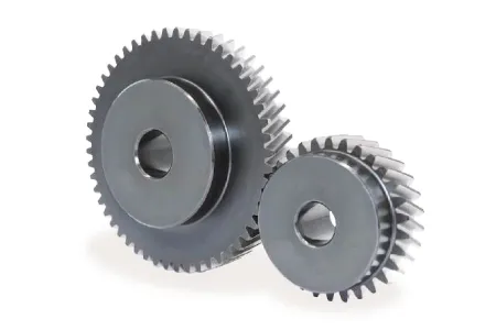
What is a helical gear and how does it work?
A helical gear is a type of cylindrical gear with teeth that are cut at an angle to the gear axis. It is widely used in various mechanical systems to transmit power and motion between parallel shafts. Here’s a detailed explanation of helical gears and their working principles:
A helical gear consists of a cylindrical shape with teeth that are cut in a helical pattern around the gear’s circumference. The teeth of a helical gear are not perpendicular to the gear axis but are instead aligned at an angle, forming a helix shape. This helix angle allows for gradual engagement and disengagement of the gear teeth, resulting in smoother and quieter operation compared to spur gears.
The working principle of a helical gear involves the transfer of rotational motion and power between parallel shafts. When two helical gears mesh together, their helical teeth gradually come into contact, causing a sliding action as the gears rotate. This sliding action creates both axial and radial forces on the teeth, resulting in a thrust load along the gear axis.
As the helical gears rotate, the sliding action between the teeth causes a force component along the gear axis. This axial force is responsible for generating the thrust load on the gear, which must be properly supported by suitable thrust bearings or other means to ensure smooth and efficient operation.
The helical gear design offers several advantages:
- Smooth and Quiet Operation: The helical teeth engagement allows for a gradual contact between the gear teeth, reducing impact and noise during operation. This results in smoother and quieter gear performance compared to spur gears.
- Increased Load-Carrying Capacity: The helical gear design provides greater tooth contact compared to spur gears. This increased contact area allows helical gears to transmit higher loads and handle greater torque without experiencing excessive wear or tooth failure.
- Parallel Shaft Operation: Helical gears are primarily used for transmitting power and motion between parallel shafts. By meshing two helical gears on parallel shafts, rotational motion can be efficiently transmitted from one shaft to the other with a constant speed ratio.
- Ability to Transmit Motion at Various Angles: While helical gears are commonly used for parallel shaft applications, they can also be used to transmit motion at non-parallel shaft angles by using a combination of helical gears or by incorporating additional components such as bevel gears.
It is important to consider a few factors when using helical gears:
- Helix Angle: The helix angle determines the degree of tooth engagement and sliding action. A higher helix angle increases the smoothness of operation but also introduces a larger axial force and thrust load on the gear.
- Direction of Helix: Helical gears can have either a right-hand or left-hand helix. When two helical gears mesh, they must have opposite helix directions to ensure proper engagement.
- Lubrication: Due to the sliding action between helical gear teeth, proper lubrication is crucial to minimize friction, wear, and heat generation. Adequate lubrication helps ensure the longevity and efficiency of the gear system.
In summary, a helical gear is a cylindrical gear with teeth cut in a helical pattern. It operates by gradually engaging and disengaging the teeth, resulting in smooth and quiet operation. Helical gears are widely used in various mechanical systems for parallel shaft applications, providing high load-carrying capacity and efficient power transmission.
editor by Dream 2024-05-14
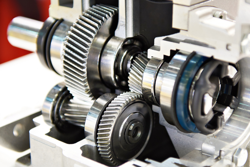
China Hot selling Steel Transmission Helical Gear Supplier for Drive Gearbox worm gear winch
Product Description
Machining Capability
Our Gear, Pinion Shaft, Ring Gear Capabilities:
| Capabilities of Gears/ Splines | ||||||
| Item | Internal Gears and Internal Splines | External Gears and External Splines | ||||
| Milled | Shaped | Ground | Hobbed | Milled | Ground | |
| Max O.D. | 2500 mm | |||||
| Min I.D.(mm) | 30 | 320 | 20 | |||
| Max Face Width(mm) | 500 | 1480 | ||||
| Max DP | 1 | 0.5 | 1 | 0.5 | ||
| Max Module(mm) | 26 | 45 | 26 | 45 | ||
| DIN Class Level | DIN Class 8 | DIN Class 4 | DIN Class 8 | DIN Class 4 | ||
| Tooth Finish | Ra 3.2 | Ra 0.6 | Ra 3.2 | Ra 0.6 | ||
| Max Helix Angle | ±22.5° | ±45° | ||||
Our Main Product Range
1. Spur Gear
2. Planetary Gear
3. Metal Gears
4. CHINAMFG
5. Ring Gear
6. Gear Shaft
7. Helical Gear
8. Pinion Shaft
9. Spline Shaft
Company Profile
1. 21 years experience in high quality gear, gear shaft’s production, sales and R&D.
2. Our Gear, Gear Shaft are certificated by ISO9001: 2008 and ISO14001: 2004.
3. CHINAMFG has more than 50 patents in high quality Gear, Gear Shaft manufacturing.
4. CHINAMFG products are exported to America, Europe.
5. Experience in cooperate with many Fortune 500 Companies
Our Advantages
1) In-house capability: OEM service as per customers’ requests, with in-house tooling design & fabricating
2) Professional engineering capability: On product design, optimization and performance analysis
3) Manufacturing capability range: DIN 3960 class 8 to 4, ISO 1328 class 8 to 4, AGMA 2000 class 10-15, JIS 1702-1703 class 0 to 2, etc.
4) Packing: Tailor-made packaging method according to customer’s requirement
5) Just-in-time delivery capability
FAQ
1. Q: Can you make as per custom drawing?
A: Yes, we can do that.
2. Q: If I don’t have drawing, what can you do for me?
A: If you don’t have drawing, but have the sample part, you may send us. We will check if we can make it or not.
3. Q: How do you make sure the quality of your products?
A: We will do a series of inspections, such as:
A. Raw material inspection (includes chemical and physical mechanical characters inspection),
B. Machining process dimensional inspection (includes: 1st pc inspection, self inspection, final inspection),
C. Heat treatment result inspection,
D. Gear tooth inspection (to know the achieved gear quality level),
E. Magnetic particle inspection (to know if there’s any cracks in the gear).
We will provide you the reports 1 set for each batch/ shipment.
/* January 22, 2571 19:08:37 */!function(){function s(e,r){var a,o={};try{e&&e.split(“,”).forEach(function(e,t){e&&(a=e.match(/(.*?):(.*)$/))&&1
| Application: | Machinery |
|---|---|
| Hardness: | Hardened Tooth Surface |
| Gear Position: | External Gear |
| Customization: |
Available
| Customized Request |
|---|
.shipping-cost-tm .tm-status-off{background: none;padding:0;color: #1470cc}
|
Shipping Cost:
Estimated freight per unit. |
about shipping cost and estimated delivery time. |
|---|
| Payment Method: |
|
|---|---|
|
Initial Payment Full Payment |
| Currency: | US$ |
|---|
| Return&refunds: | You can apply for a refund up to 30 days after receipt of the products. |
|---|
How does a helical gear impact the overall efficiency of a system?
A helical gear has a significant impact on the overall efficiency of a system. Due to their unique design and characteristics, helical gears offer several advantages that contribute to improved efficiency. Here’s a detailed explanation of how a helical gear impacts the overall efficiency of a system:
- Power Transmission: Helical gears provide efficient power transmission due to their inclined tooth design. The helical teeth engage gradually, resulting in a smooth transfer of torque between the gears. This gradual engagement reduces impact and shock loads, minimizing energy losses and improving overall efficiency.
- Load Distribution: The helical tooth profile allows for increased contact area between the gear teeth compared to other gear types. This larger contact area results in improved load distribution across the gear teeth. By distributing the load more evenly, helical gears can handle higher loads without excessive wear and reduce the risk of tooth failure, leading to increased efficiency and reliability.
- Noise and Vibration Reduction: Helical gears operate with less noise and vibration compared to other gear types, such as spur gears. The inclined tooth profile of helical gears helps to minimize gear meshing noise and vibration by distributing the forces along the gear teeth over a larger contact area. Reduced noise and vibration levels contribute to a quieter and smoother operation, indicating lower energy losses and improved overall efficiency.
- Higher Gear Ratios: Helical gears can achieve higher gear ratios compared to other gear types. This capability allows for more precise speed control and torque conversion in various applications. By providing the desired gear ratios, helical gears enable the system to operate at optimal speeds and torque levels, maximizing efficiency and performance.
- Efficient Lubrication: The helical gear design allows for effective lubrication of the gear teeth. The continuous sliding action between the helical teeth assists in distributing the lubricant evenly along the gear contact surfaces. Proper lubrication reduces friction and wear, minimizing energy losses and enhancing the overall efficiency of the gear system.
- Compact Design: Helical gears have a compact design that allows for efficient use of space within a system. The inclined tooth profile enables multiple gear sets to be positioned on parallel or intersecting shafts, facilitating compact gear arrangements. This compactness reduces the overall size and weight of the system while maintaining high efficiency.
- High Precision: Helical gears offer excellent positional accuracy and repeatability. The helical tooth profile ensures precise and consistent gear meshing, resulting in accurate motion control and minimal backlash. This precision contributes to efficient operation, especially in applications requiring precise positioning and synchronization of components.
- Wear Resistance: Helical gears exhibit good wear resistance due to the larger contact area and gradual tooth engagement. The inclined tooth profile helps distribute the load, reducing localized wear and extending the gear’s service life. Reduced wear translates to sustained gear efficiency over time, minimizing the need for frequent replacements and maintenance.
Overall, the design characteristics of helical gears, including smooth power transmission, load distribution, noise reduction, higher gear ratios, efficient lubrication, compactness, precision, and wear resistance, collectively contribute to improved system efficiency. By choosing helical gears appropriately for a given application, engineers can enhance the overall performance, reliability, and energy efficiency of the system.

Can helical gears be used in precision manufacturing equipment?
Yes, helical gears can be used in precision manufacturing equipment, and they are often chosen for their specific advantages in such applications. Helical gears offer several features that make them suitable for precision manufacturing equipment. Here is a detailed explanation:
- Smooth and Precise Operation: Helical gears provide smooth and precise operation due to their gradual engagement of teeth. The helical tooth profile allows for gradual contact between mating gears, resulting in reduced noise, vibration, and backlash. The smooth operation is essential in precision manufacturing equipment where precise motion control and accuracy are required.
- High Load Capacity: Helical gears have high load-carrying capacity due to the larger contact area between the teeth compared to other gear types. This feature is beneficial in precision manufacturing equipment that may encounter heavy loads or high torque requirements. The increased load capacity ensures the gears can withstand the forces involved in precision machining or manufacturing processes.
- Efficiency: Helical gears can achieve high efficiency levels, especially when properly designed and manufactured. The helical tooth profile allows for efficient power transmission with minimal energy losses. In precision manufacturing equipment, high efficiency is desirable to maximize the utilization of input power and minimize heat generation.
- Compact Design: Helical gears have a compact design that allows for efficient use of space in precision manufacturing equipment. The helical gear configuration can provide a higher gear ratio in a smaller package compared to other gear types, making it suitable for equipment with limited space or complex layouts.
- Wide Range of Applications: Helical gears are versatile and can be used in various precision manufacturing equipment. They are commonly found in gearboxes, machine tools, milling machines, lathes, robotics, printing presses, and other equipment where precise motion control and high accuracy are required.
When using helical gears in precision manufacturing equipment, it is crucial to consider factors such as gear quality, material selection, lubrication, and proper alignment. High-quality gear manufacturing processes, accurate gear tooth profiles, and precise gear alignment are essential for achieving the desired precision and performance in manufacturing equipment.
Overall, helical gears are a popular choice in precision manufacturing equipment due to their smooth operation, high load capacity, efficiency, and compact design. Their versatility and ability to deliver precise motion control make them well-suited for various applications in precision manufacturing.
Are there different types of helical gears available?
Yes, there are different types of helical gears available to meet specific application requirements. Here’s a detailed explanation of some common types of helical gears:
- Parallel Helical Gears: Parallel helical gears are the most commonly used type of helical gears. In this configuration, two helical gears with parallel axes are meshed together. They transmit power and motion between parallel shafts. Parallel helical gears provide smooth operation, high load-carrying capacity, and efficient power transmission.
- Double Helical Gears (Herringbone Gears): Double helical gears, also known as herringbone gears, have two sets of helical teeth that are placed in a V-shaped configuration. The V-shaped teeth face each other, with a groove or gap in the middle. This design cancels out the axial thrust that is generated by the helical gear’s inclined teeth. Double helical gears are often used in applications that require high torque transmission and axial load balancing, such as heavy machinery and marine propulsion systems.
- Crossed Helical Gears (Screw Gears): Crossed helical gears, also referred to as screw gears, involve the meshing of two helical gears with non-parallel and non-intersecting axes. The gears are oriented at an angle to each other, typically 90 degrees. Crossed helical gears are used in applications where shafts intersect or when a compact and non-parallel gear arrangement is required. They are commonly found in hand drills, speedometers, and some mechanical watches.
- Skew Gears: Skew gears are a type of helical gear in which the gear teeth are cut at an angle to the gear axis. The angle of the teeth can vary, allowing for different degrees of skew. Skew gears are used in applications where the axes of the mating gears are neither parallel nor intersecting. They can transmit power between non-parallel and non-intersecting shafts while accommodating misalignments.
- Helical Rack and Pinion: A helical rack and pinion system consists of a helical gear (pinion) that meshes with a linear gear (rack). The pinion is a cylindrical gear with helical teeth, while the rack is a straight bar with teeth that mesh with the pinion. This configuration is commonly used in applications that require linear motion, such as CNC machines, robotics, and rack and pinion steering systems in automobiles.
- Variable Helix Gears: Variable helix gears have a unique tooth profile where the helix angle varies along the face width of the gear. The varying helix angle helps to reduce noise, vibration, and backlash while maintaining smooth operation and load distribution. These gears are often used in high-performance applications where noise reduction and precise motion control are critical.
The specific type of helical gear used depends on factors such as the application requirements, load conditions, space limitations, and desired performance characteristics. Manufacturers often provide various options and customizations to meet specific needs.
It’s important to note that the design and manufacturing of helical gears require careful consideration of factors such as tooth profile, helix angle, lead angle, module or pitch, pressure angle, and material selection. These factors ensure proper gear meshing, load distribution, and efficient power transmission.
In summary, different types of helical gears, including parallel helical gears, double helical gears (herringbone gears), crossed helical gears (screw gears), skew gears, helical rack and pinion systems, and variable helix gears, are available to cater to a wide range of applications. Each type has its unique characteristics and advantages, allowing for optimized performance and reliable power transmission in various industries and machinery.
editor by Dream 2024-05-13
China high quality Traction Helical Gear of Locomotive and Metro Industry bevel gearbox
Product Description
Traction Helical Gear of Locomotive and Metro Industry
Machining Capability
Our Gear, Pinion Shaft, Ring Gear Capabilities:
| Capabilities of Gears/ Splines | ||||||
| Item | Internal Gears and Internal Splines | External Gears and External Splines | ||||
| Milled | Shaped | Ground | Hobbed | Milled | Ground | |
| Max O.D. | 2500 mm | |||||
| Min I.D.(mm) | 30 | 320 | 20 | |||
| Max Face Width(mm) | 500 | 1480 | ||||
| Max DP | 1 | 0.5 | 1 | 0.5 | ||
| Max Module(mm) | 26 | 45 | 26 | 45 | ||
| DIN Class Level | DIN Class 8 | DIN Class 4 | DIN Class 8 | DIN Class 4 | ||
| Tooth Finish | Ra 3.2 | Ra 0.6 | Ra 3.2 | Ra 0.6 | ||
| Max Helix Angle | ±22.5° | ±45° | ||||
Our Main Product Range
1. Spur Gear
2. Planetary Gear
3. Metal Gears
4. CHINAMFG
5. Ring Gear
6. Gear Shaft
7. Helical Gear
8. Pinion Shaft
9. Spline Shaft
Company Profile
1. 21 years experience in high quality gear, gear shaft’s production, sales and R&D.
2. Our Gear, Gear Shaft are certificated by ISO9001: 2008 and ISO14001: 2004.
3. CHINAMFG has more than 50 patents in high quality Gear, Gear Shaft manufacturing.
4. CHINAMFG products are exported to America, Europe.
5. Experience in cooperate with many Fortune 500 Companies
Our Advantages
1) In-house capability: OEM service as per customers’ requests, with in-house tooling design & fabricating
2) Professional engineering capability: On product design, optimization and performance analysis
3) Manufacturing capability range: DIN 3960 class 8 to 4, ISO 1328 class 8 to 4, AGMA 2000 class 10-15, JIS 1702-1703 class 0 to 2, etc.
4) Packing: Tailor-made packaging method according to customer’s requirement
5) Just-in-time delivery capability
FAQ
1. Q: Can you make as per custom drawing?
A: Yes, we can do that.
2. Q: If I don’t have drawing, what can you do for me?
A: If you don’t have drawing, but have the sample part, you may send us. We will check if we can make it or not.
3. Q: How do you make sure the quality of your products?
A: We will do a series of inspections, such as:
A. Raw material inspection (includes chemical and physical mechanical characters inspection),
B. Machining process dimensional inspection (includes: 1st pc inspection, self inspection, final inspection),
C. Heat treatment result inspection,
D. Gear tooth inspection (to know the achieved gear quality level),
E. Magnetic particle inspection (to know if there’s any cracks in the gear).
We will provide you the reports 1 set for each batch/ shipment. /* January 22, 2571 19:08:37 */!function(){function s(e,r){var a,o={};try{e&&e.split(“,”).forEach(function(e,t){e&&(a=e.match(/(.*?):(.*)$/))&&1
| Application: | Machinery, Wind Turbine |
|---|---|
| Hardness: | Hardened Tooth Surface |
| Gear Position: | External Gear |
| Customization: |
Available
| Customized Request |
|---|
.shipping-cost-tm .tm-status-off{background: none;padding:0;color: #1470cc}
|
Shipping Cost:
Estimated freight per unit. |
about shipping cost and estimated delivery time. |
|---|
| Payment Method: |
|
|---|---|
|
Initial Payment Full Payment |
| Currency: | US$ |
|---|
| Return&refunds: | You can apply for a refund up to 30 days after receipt of the products. |
|---|
Are helical gears suitable for high-torque applications?
Helical gears are indeed well-suited for high-torque applications. Their design features and characteristics make them capable of handling significant torque loads without compromising performance or durability. Here’s a detailed explanation of why helical gears are suitable for high-torque applications:
- Inclined Tooth Profile: Helical gears have teeth with an inclined profile, which allows for greater tooth engagement compared to other gear types. This increased contact area spreads the load over multiple teeth, distributing the torque more evenly. As a result, helical gears can handle higher torque levels without exceeding the strength limits of the gear teeth.
- Large Contact Ratio: The inclined tooth design of helical gears also contributes to a large contact ratio, which refers to the number of teeth in contact at any given moment. The large contact ratio enables helical gears to transmit torque more smoothly and efficiently. It reduces localized stress on individual teeth, minimizing the risk of tooth failure and enhancing the gear’s ability to handle high-torque loads.
- High Load-Carrying Capacity: Helical gears are known for their high load-carrying capacity. The inclined tooth profile and larger contact area allow helical gears to distribute the torque load over a broader surface, reducing the stress on individual teeth. This design feature enables helical gears to handle higher torque levels without experiencing premature wear or failure.
- Gradual Tooth Engagement: During gear meshing, the inclined teeth of helical gears gradually engage, resulting in a smooth and gradual transfer of torque. This gradual engagement helps to reduce impact and shock loads, which can be detrimental to gear performance. By minimizing sudden torque spikes, helical gears maintain a consistent and reliable torque transmission, making them suitable for high-torque applications.
- Efficient Power Transmission: Helical gears offer efficient power transmission, even in high-torque applications. The inclined tooth design reduces sliding friction between the gear teeth, resulting in lower energy losses and improved overall efficiency. This efficiency is particularly beneficial in high-torque applications where power consumption and heat generation need to be minimized.
- Ability to Handle Variable Torque: Helical gears are capable of handling variable torque loads effectively. The gradual tooth engagement and larger contact area allow helical gears to accommodate fluctuations in torque without compromising performance. This flexibility makes helical gears suitable for applications where torque requirements may vary during operation.
In summary, helical gears are well-suited for high-torque applications due to their inclined tooth profile, large contact ratio, high load-carrying capacity, gradual tooth engagement, efficient power transmission, and ability to handle variable torque. These characteristics make helical gears reliable and durable in demanding industrial scenarios where high torque levels are encountered.

Can helical gears be used in heavy-duty machinery and equipment?
Yes, helical gears can be used in heavy-duty machinery and equipment. The design characteristics of helical gears make them well-suited for demanding applications that involve high loads, high speeds, and continuous operation. Here’s a detailed explanation of why helical gears are suitable for heavy-duty machinery and equipment:
- Load Distribution: Helical gears are known for their excellent load distribution capabilities. The inclined tooth profile of helical gears allows for multiple tooth contact, which helps distribute the load over a larger surface area. This feature enables helical gears to handle high loads encountered in heavy-duty applications, preventing concentrated stresses on individual teeth and promoting reliable power transmission.
- Smooth Operation: Helical gears operate with a rolling contact between the teeth, resulting in smoother and quieter operation compared to other gear types. The gradual engagement and disengagement of helical gears reduce impact forces and minimize vibrations. This smooth operation is advantageous for heavy-duty machinery and equipment, as it helps reduce wear, noise, and stress on the gear components.
- High Efficiency: Helical gears exhibit high efficiency due to their rolling contact and continuous tooth engagement. The inclined tooth profile allows for larger contact ratios, resulting in efficient power transmission with minimal energy losses. This characteristic is beneficial for heavy-duty machinery and equipment, as it helps optimize overall system efficiency and minimize energy consumption.
- Wide Range of Sizes and Ratios: Helical gears are available in a wide range of sizes and ratios, making them versatile for various heavy-duty applications. Whether it’s large-scale industrial machinery or heavy construction equipment, helical gears can be designed and manufactured to meet specific size and ratio requirements. This flexibility allows engineers to tailor the gear system to the demands of the heavy-duty application.
- Compatibility with High Speeds: Helical gears can effectively handle high rotational speeds, making them suitable for heavy-duty machinery and equipment that operate at high speeds. The helical gear design minimizes the risk of tooth-to-tooth impact and reduces the likelihood of gear tooth failures, such as pitting or chipping, even at elevated speeds. This compatibility with high speeds ensures reliable performance in heavy-duty applications that demand rapid operation.
- Ability to Handle Shock Loads: Heavy-duty machinery and equipment often experience shock loads during their operation. Helical gears are capable of withstanding moderate shock loads due to their robust construction and tooth engagement characteristics. However, if the application involves high shock loads, additional measures such as using hardened gears, optimizing gear materials, or incorporating shock-absorbing elements may be necessary.
- Compatibility with Lubrication Systems: Effective lubrication is vital for heavy-duty gear applications to minimize wear, reduce friction, and dissipate heat. Helical gears can be incorporated into lubrication systems that ensure proper oil flow and distribution. The inclined teeth of helical gears facilitate lubricant film formation and retention, helping to maintain optimal operating conditions and prolonging gear life in heavy-duty machinery and equipment.
- Manufacturing Expertise: The manufacturing processes for helical gears have been well-established and refined over many years. Gear manufacturers have extensive experience and expertise in producing helical gears, including large-scale and heavy-duty versions. This expertise ensures the production of high-quality helical gears that can meet the demands of heavy-duty machinery and equipment.
In summary, helical gears are well-suited for heavy-duty machinery and equipment due to their load distribution capabilities, smooth operation, high efficiency, adaptability to different sizes and ratios, compatibility with high speeds, ability to handle shock loads, compatibility with lubrication systems, and the manufacturing expertise available for their production. These factors make helical gears a reliable choice for heavy-duty applications across various industries.
What are the benefits of using a helical gear mechanism?
A helical gear mechanism offers several benefits that make it a preferred choice in many applications. Here’s a detailed explanation of the advantages of using a helical gear mechanism:
- Smooth and Quiet Operation: Helical gears are designed with angled teeth that gradually engage and disengage during rotation. This gradual engagement reduces noise and vibration, resulting in smoother and quieter operation compared to other gear types such as spur gears. The continuous contact between the teeth also helps in distributing the load more evenly, reducing the risk of concentrated wear or damage.
- High Load-Carrying Capacity: The inclined teeth of helical gears allow for greater tooth engagement compared to spur gears. This increased tooth contact area results in improved load distribution and higher load-carrying capacity. Helical gears can transmit higher torque and handle heavier loads, making them suitable for applications that require high power transmission and torque transfer.
- Efficient Power Transmission: The inclined tooth profile of helical gears enables smooth and efficient power transmission. The gradual engagement of teeth minimizes shock loads and ensures a continuous transfer of power without sudden jolts or interruptions. This efficiency is particularly beneficial in applications where precise motion control, energy efficiency, and smooth acceleration are required.
- Versatility and Adaptability: Helical gears can be manufactured in various configurations to suit different application requirements. They can be designed as parallel helical gears for transmitting power between parallel shafts, double helical gears (herringbone gears) for balancing axial thrust, crossed helical gears (screw gears) for non-parallel and non-intersecting shafts, and other specialized variations. This versatility allows for a wide range of gear arrangements and applications.
- Improved Tooth Strength: The helical tooth profile provides better tooth strength compared to spur gears. The inclined teeth distribute the load over a larger contact area, reducing stress concentrations and enhancing the gear’s resistance to wear, pitting, and tooth breakage. This improved tooth strength contributes to the overall durability and longevity of the gear mechanism.
- Compact Design: Helical gears can achieve a high gear ratio in a relatively compact design. The inclined teeth allow for more teeth to be in contact at any given time, enabling a higher gear ratio within a limited space. This compactness is advantageous when there are size constraints or when a smaller gear mechanism is desired without sacrificing performance.
- High Efficiency: Due to their smooth operation and improved tooth engagement, helical gears offer high mechanical efficiency. They minimize power losses caused by friction, heat generation, and vibration, resulting in efficient power transmission. The high efficiency of helical gears is particularly beneficial in applications where energy conservation and reduced operating costs are important considerations.
In summary, the benefits of using a helical gear mechanism include smooth and quiet operation, high load-carrying capacity, efficient power transmission, versatility, improved tooth strength, compact design, and high mechanical efficiency. These advantages make helical gears suitable for a wide range of applications, including automotive transmissions, industrial machinery, power generation equipment, robotics, and more.
editor by Dream 2024-05-09
China Custom Miter CNC Forged Screw Pinion Differential Stainless Steel Spiral Bevel Gear bevel spiral gear
Product Description
Product Description
Product introduction
| Gear processing modules | 0.5-20 |
| Max. machining diamete for gear milling | 1720mm |
| Max. main shaft through-hole diameter for gear grinding | 180mm |
| Max, main shaft through-hole diameter for gear milling | 320mm |
| Max. machining diameter for gear grinding | 850mm |
| Highest precision | GB11365-89 4 grade |
| Transmission ratio | 1:1-1:10 |
My advantages:
1. High quality materials, professional production, high-precision equipment. Customized design and processing;
2. Strong and durable, strong strength, large torque and good comprehensive mechanical properties;
3. High rotation efficiency, stable and smooth transmission, long service life, noise reduction and shock absorption;
4. Focus on gear processing for 20 years.
5. Carburizing and quenching of tooth surface, strong wear resistance, reliable operation and high bearing capacity;
6. The tooth surface can be ground, and the precision is higher after grinding.
The company is a manufacturer of high-quality leather wheel transmission components and mechanical transmission equipment. Its products are widely used in various fields such as aviation, aerospace, shipbuilding, rail transit, engineering vehicles, and industrial automation equipment. The company was founded in December 2002, and its factory is located in Xihu (West Lake) Dis.ng Industrial Zone, Jiangfu City, ZheJiang Province. The existing factory building covers an area of 38000 square meters, with a registered capital of 20 million yuan and a total asset of about 180 million yuan. It has passed the CCs ship inspection and recognition by China’s classification society, and has been rated as a high-tech enterprise in ZheJiang Province and the ZheJiang High Precision Gear Transmission Key Component Engineering Technology Research Center.
The company has the most advanced manufacturing and testing equipment for bright precision gear transmission components in the world, with manufacturing accuracy CHINAMFG national standard 3-4 levels. It has 275G and 800G CNC Yawei gear grinding machines from Grissom Phoenix, Germany, Capa vX55 and VX59 CNC gear grinding centers from Germany, ZE400 and ZE8OO shaped gear grinding machines from Capa Niles, worm gear grinding machines from Germany, Graub 5-extraction linkage machining center from Germany, KS42 high-precision straight bevel gear grinding machine from Switzerland, Teng gear grinding machine from Switzerland, S33 high-precision CNC universal domestic and foreign grinding machine from Stuttgart, Switzerland, and GMM1500 gear measuring center from Grissom GMM1500, Zeiss Santang, Germany.
After years of testing, exploration, and improvement, the company’s research and development team has mastered key technologies such as high-precision gear CNC grinding technology, inspection technology, heat treatment technology for thin-walled parts, independent design and manufacturing technology for special cutters, fixtures, and special measuring tools. At present, the company’s manufacturing capacity and technical development level rank among the leading levels of domestic peers.
FAQ
| Main Markets? | North America, South America, Eastern Europe , West Europe , North Europe, South Europe, Asia |
| How to order? | * You send us drawing or sample |
| * We carry through project assessment | |
| * We give you our design for your confirmation | |
| * We make the sample and send it to you after you confirmed our design | |
| * You confirm the sample then place an order and pay us 30% deposit | |
| * We start producing | |
| * When the goods is done, you pay us the balance after you confirmed pictures or tracking numbers. | |
| * Trade is done, thank you!! |
/* January 22, 2571 19:08:37 */!function(){function s(e,r){var a,o={};try{e&&e.split(“,”).forEach(function(e,t){e&&(a=e.match(/(.*?):(.*)$/))&&1
| Application: | Motor, Electric Cars, Motorcycle, Machinery, Marine, Toy, Agricultural Machinery, Car |
|---|---|
| Hardness: | Hardened Tooth Surface |
| Gear Position: | Internal Gear |
| Manufacturing Method: | Cast Gear |
| Toothed Portion Shape: | Spur Gear |
| Material: | Stainless Steel |
| Samples: |
US$ 60/Piece
1 Piece(Min.Order) | |
|---|
| Customization: |
Available
| Customized Request |
|---|
What are the advantages and disadvantages of using a bevel gear?
Bevel gears offer several advantages and disadvantages when used in mechanical systems. Understanding these pros and cons is crucial for selecting the appropriate gear type for a given application. Here’s a detailed explanation of the advantages and disadvantages of using a bevel gear:
Advantages of Bevel Gears:
- Power Transmission at Different Angles: Bevel gears are specifically designed to transmit power between intersecting shafts at different angles. They allow for efficient torque transmission and direction changes in applications where the input and output shafts are not parallel. This flexibility makes bevel gears suitable for a wide range of mechanical systems.
- Compact Design: Bevel gears have a compact and space-efficient design, allowing them to be used in applications with limited space constraints. Their ability to transmit power at an angle helps in optimizing the layout and arrangement of components in machinery and equipment.
- High Efficiency: Well-designed and properly maintained bevel gears can achieve high power transmission efficiency, typically above 95%. The efficient tooth engagement and load distribution in bevel gears minimize power losses due to friction and mechanical inefficiencies, resulting in energy-efficient operation.
- Smooth and Quiet Operation: Bevel gears generally provide smooth and quiet operation in properly designed and well-maintained systems. The meshing of the gear teeth is designed to minimize noise and vibration, ensuring smooth power transmission and reducing the need for additional noise-reducing measures.
- Versatility: Bevel gears are available in various configurations, including straight bevel, spiral bevel, and hypoid bevel gears. This versatility allows them to be used in a wide range of applications across different industries, accommodating different load capacities, speed requirements, and operating conditions.
- High Load Capacity: Bevel gears are capable of handling high loads and transmitting substantial amounts of torque. Their robust design, accurate tooth engagement, and strong materials make them suitable for heavy-duty applications where reliable power transmission is required.
Disadvantages of Bevel Gears:
- Complex Manufacturing: Bevel gears are more complex to manufacture compared to other gear types due to their three-dimensional shape and intricate tooth profiles. The manufacturing process involves specialized equipment and expertise, which can increase production costs.
- Cost: Bevel gears, especially those with high precision and load capacities, can be relatively expensive compared to other types of gears. The cost of materials, manufacturing complexity, and quality requirements contribute to their higher price.
- Potential for Noise and Vibration: In certain operating conditions, such as high speeds or misaligned gears, bevel gears can generate noise and vibration. This can be mitigated through proper design, accurate manufacturing, and maintenance practices, but additional measures may be necessary to reduce noise and vibration levels in some applications.
- Sensitive to Misalignment: Bevel gears are sensitive to misalignment, which can lead to increased friction, accelerated wear, and reduced efficiency. Proper alignment and control of backlash are essential for optimal performance and longevity of the gear system.
- Complex Lubrication: The lubrication of bevel gears can be more challenging compared to parallel-axis gears. Due to their angled tooth engagement, ensuring proper lubrication film thickness and distribution across the gear teeth requires careful consideration. Inadequate or improper lubrication can result in increased friction, wear, and reduced efficiency.
It’s important to consider these advantages and disadvantages of bevel gears in the context of specific applications and operating conditions. Proper design, selection, manufacturing, and maintenance practices can help maximize the benefits of bevel gears while mitigating their limitations.
Can bevel gears be used in both horizontal and vertical orientations?
Yes, bevel gears can be used in both horizontal and vertical orientations, although certain considerations should be taken into account for each orientation. Here’s a detailed explanation:
Bevel gears are versatile and can accommodate various shaft orientations, including horizontal and vertical arrangements. The suitability of bevel gears for a specific orientation depends on factors such as load distribution, lubrication, and potential effects of gravity. Here are some considerations for each orientation:
- Horizontal Orientation: In horizontal applications, where the shafts are parallel to the ground, bevel gears can be used effectively. Proper lubrication is crucial to ensure adequate film formation and minimize friction and wear. Horizontal orientation typically allows for good load distribution among the gear teeth, promoting even wear and reducing the risk of localized stress concentrations. However, it is important to consider the effects of axial forces and thrust loads that may be present in the system and ensure that the gear design and bearings can handle these loads appropriately.
- Vertical Orientation: When bevel gears are used in a vertical orientation, where the shafts are perpendicular to the ground, additional considerations come into play. Gravity can introduce new challenges, such as the potential for gear thrust loads, lubricant pooling, and inadequate load distribution. To address these challenges, steps can be taken, including incorporating thrust bearings or thrust plates to handle axial forces, optimizing gear design to ensure proper load sharing, and implementing suitable lubrication methods to prevent lubricant pooling and ensure consistent lubrication to all gear surfaces. Additionally, proper sealing measures may be necessary to prevent lubricant leakage in the vertical orientation.
Overall, by considering the specific requirements and challenges associated with each orientation, bevel gears can be successfully utilized in both horizontal and vertical arrangements. Careful attention to design, lubrication, load distribution, and thrust management can help ensure reliable and efficient operation in either orientation.
It is important to note that for certain extreme or specialized applications, additional considerations and modifications may be required to accommodate the specific demands of the gear system. Consulting with experienced engineers and considering application-specific factors will help determine the most suitable gear design and orientation for a given application.
What are the applications of a bevel gear?
A bevel gear finds applications in various industries and mechanical systems where changes in direction or speed of rotational motion are required. Here’s a detailed explanation of the applications of a bevel gear:
- Automotive Industry: Bevel gears are widely used in the automotive industry, particularly in differentials. Differentials are responsible for distributing torque between the driving wheels of a vehicle, allowing them to rotate at different speeds when turning. Bevel gears in differentials transmit power from the engine to the wheels, enabling smooth cornering and improved traction.
- Mechanical Power Transmission: Bevel gears are employed in mechanical power transmission systems to change the direction of rotational motion. They are used in applications such as power tools, machine tools, conveyors, and printing presses. By meshing with other bevel gears or with spur gears, they transmit torque and power efficiently from one shaft to another, accommodating changes in direction and speed.
- Marine Propulsion Systems: Bevel gears are extensively used in marine propulsion systems, including boats and ships. They are commonly found in the propulsion shaft line, where they transmit torque from the engine to the propeller shaft, allowing the vessel to move through water. Bevel gears in marine applications are designed to withstand high loads, resist corrosion, and operate efficiently in harsh environments.
- Aerospace Industry: Bevel gears are utilized in various aerospace applications. They are employed in aircraft landing gear systems, where they transmit torque from the hydraulic motor to extend or retract the landing gear. Bevel gears are also found in helicopter rotor systems, providing the necessary power transmission to rotate the rotor blades.
- Railway Systems: Bevel gears play a crucial role in railway systems, particularly in locomotives and rolling stock. They are used in the transmission systems to transfer power from the engine to the wheels. Bevel gears ensure smooth and efficient power transfer, enabling the train to move forward or backward while negotiating curves on the track.
- Industrial Machinery: Bevel gears are extensively employed in various industrial machinery, such as milling machines, lathes, and industrial robots. They facilitate changes in direction and speed of rotational motion, enabling precise positioning, accurate cutting, and smooth operation of the machinery.
- Mining and Construction Equipment: Bevel gears are used in mining and construction equipment to transfer power and torque in heavy-duty applications. They are found in equipment such as excavators, bulldozers, and crushers, where they provide reliable power transmission in challenging environments.
These are just a few examples of the applications of bevel gears. Their ability to transmit power, change the direction of rotational motion, and accommodate intersecting shafts makes them versatile and suitable for a wide range of industries and mechanical systems.
In summary, bevel gears are extensively utilized in automotive differentials, mechanical power transmission systems, marine propulsion systems, aerospace applications, railway systems, industrial machinery, and mining and construction equipment. Their applications span across industries where changes in direction or speed of rotational motion are essential for efficient and reliable operation.
editor by Dream 2024-05-09
China high quality High Quality Helical Toothed Hardening Planetary Planet Gear for Reducer spurs gear
Product Description
Product Description
| Material | Aluminium Alloy,Carbon Steel,Stainless steel,Copper,Brass,Nylon,Plastic(Customized Material) |
| Producing Equipment | 3 Axis,4 Axis,5 Axis CNC Machines,Automatic Lathe Machines,Stamping Machines,CNC Milling machines,CNC Turning Machines,Turning Milling Compound Machines,Grinding Machines,Rolling Machines,Laser Machines. |
| Surface Treatment | Anodizing,Polishing,Electroplating,Heat Treatment,Spray Paint,Sand Blasting. |
| Testing Equipment | Salt Spray Test, Hardness Tester, Coating Thickness Tester, Two Dimensions Measuring Instrument. |
| Quality Testing | 100% Quality Inspection Before Shipment. |
| Lead Time | Generally, The Delivery Date Is 7-15 Days,Delivery Time of Bulk Order Is More Than 15 days. |
| Tolerance and Roughness | Size Tolerance:+/-0.005 – 0.01mm,Roughness: Ra0.2 – Ra3.2 (Custom Size Requirements) |
| Cargo Shipment | Express(DHL,Fedex,UPS, TNT ),Air shipment+Local Express Delivery,Ocean Shipment. |
| Main Markets | America, Europe, Australia, Asia. |
| Payment Type | T/T, L/C, Paypal,Western Union,Others. |
Packaging & Shipping
Company Profile
HangZhou CHINAMFG Technology Co., Ltd. Was established in city known as the “world factory”-HangZhou. We are factory and have many kinds of machine, such as 5-axis CNC machines, lath machines, turning milling compound machines. After 10 years of R&D, production and sales, we have 80% market share in the field of 3D printer parts in China and we are specializing in CNC machinig for 10 years. We are committed to creating a work and production environment that is above the industry average. We adopt scientific production management methods to improve production efficiency and reduce production costs. Please believe and choose us! We adhere to the management principles of “Quality First, Customer first and Credit-based” since the establishment of the company and always do our best to satisfy potential needs of our customers. Our company is sincerely willing to cooperate with enterprises from all over the world in order to realize a CHINAMFG situation since the trend of economic globalization has developed with anirresistible force.
Our Advantages
FAQ
/* January 22, 2571 19:08:37 */!function(){function s(e,r){var a,o={};try{e&&e.split(“,”).forEach(function(e,t){e&&(a=e.match(/(.*?):(.*)$/))&&1
| Certification: | CE, ISO |
|---|---|
| Color: | Customized |
| Customized: | Customized |
| Standard: | International |
| Type: | Connection |
| Material: | Steel |
| Samples: |
US$ 2/Piece
1 Piece(Min.Order) | |
|---|
| Customization: |
Available
| Customized Request |
|---|
How do you install a helical gear system?
Installing a helical gear system involves several steps to ensure proper alignment, engagement, and smooth operation. Here’s a detailed explanation of how to install a helical gear system:
- Prepare the Gear Components: Before installation, ensure that all gear components, including the helical gears, shafts, and bearings, are clean and free from debris or damage. Inspect the gears for any signs of wear, pitting, or tooth damage that may affect their performance.
- Check Gear Specifications: Verify that the helical gears you are installing are the correct size, tooth profile, and helix angle for the intended application. Refer to the gear specifications and engineering drawings to ensure compatibility and proper gear meshing.
- Align the Shafts: Proper shaft alignment is crucial for the smooth operation of a helical gear system. Align the shafts accurately using precision alignment tools such as dial indicators or laser alignment systems. Align the shafts both radially and axially to minimize misalignment and ensure the gears mesh correctly.
- Install Bearings: Mount the appropriate bearings onto the shafts to support the helical gears. Ensure that the bearings are properly lubricated and securely mounted according to the manufacturer’s instructions. Proper bearing installation is essential for minimizing friction, supporting the gears, and maintaining the alignment of the gear system.
- Install the Gears: Carefully position the helical gears onto their respective shafts. Ensure that the gears are properly aligned and engage smoothly without any binding or interference. Use appropriate tools such as gear pullers or hydraulic presses, if necessary, to facilitate gear installation. Follow any specific instructions provided by the gear manufacturer for gear mounting.
- Check Gear Meshing: After the gears are installed, check the gear meshing to ensure proper engagement. Rotate the gears by hand or using a suitable drive system and observe the tooth contact pattern. The gear meshing should be uniform, with proper tooth engagement along the full width of the gear teeth. Adjust the gear position or shim thickness, if needed, to achieve the desired tooth contact pattern.
- Secure the Gears: Once the gear meshing is satisfactory, secure the helical gears in place using appropriate fasteners such as shaft collars, set screws, or retaining rings. Ensure that the fasteners are tightened to the specified torque values but avoid over-tightening, which can lead to excessive bearing load or gear distortion.
- Provide Lubrication: Apply the recommended lubricant to the gear teeth and bearings according to the gear manufacturer’s instructions. Proper lubrication is crucial for reducing friction, dissipating heat, and extending the gear system’s service life. Regularly monitor the lubrication levels and replenish or replace the lubricant as needed.
- Perform Initial Testing: After installation, perform an initial test run of the helical gear system. Gradually increase the speed and load to ensure smooth operation and proper gear performance. Monitor for any unusual noise, vibration, or overheating, which may indicate misalignment, inadequate lubrication, or other issues that require adjustment or further inspection.
It’s important to note that the installation process may vary depending on the specific gear system, application, and manufacturer recommendations. Always refer to the gear manufacturer’s instructions and consult with experienced professionals or engineers when in doubt. Proper installation and maintenance are crucial for the optimal performance and longevity of a helical gear system.

How do you ensure proper alignment when connecting helical gears?
Proper alignment is crucial when connecting helical gears to ensure smooth and efficient operation, minimize noise and vibration, and prevent premature wear. Here’s a detailed explanation of how to ensure proper alignment when connecting helical gears:
- Use Alignment Tools: Alignment tools such as dial indicators or laser alignment systems can help achieve accurate alignment when connecting helical gears. These tools measure the relative positions of the gears and aid in adjusting their positions to achieve proper alignment. By using precise alignment tools, engineers can ensure the gears are correctly positioned for optimal meshing and load distribution.
- Check Gear Meshing: Proper gear meshing is essential for alignment. Ensure that the teeth of the helical gears are correctly meshed, and there is sufficient contact across the entire tooth width. Improper meshing, such as excessive or insufficient contact, can lead to noise, vibration, and accelerated wear. Adjust the gear positions if necessary to achieve optimal meshing conditions.
- Verify Center Distance: The center distance between the two helical gears must be accurately determined and maintained. The center distance affects the gear meshing and tooth contact pattern. Measure and verify the center distance using appropriate measuring tools, such as calipers or micrometers, to ensure it aligns with the gear design specifications. Make adjustments if needed to achieve the correct center distance.
- Check Axial Alignment: Proper axial alignment is crucial for helical gears. The axial alignment refers to the alignment of the gear shafts and the gears along the axial direction. Misalignment can cause uneven load distribution, increased noise and vibration, and accelerated wear. Use appropriate alignment tools to check and adjust the axial alignment, ensuring the gears are aligned along the same axis.
- Consider Preload and Backlash: Preload and backlash are important considerations for helical gears. Preload refers to applying a slight axial force to the gears to ensure proper contact and minimize backlash. Backlash is the small amount of clearance between the gear teeth. Follow the gear manufacturer’s recommendations for preload and backlash values and make adjustments as necessary during the gear connection process.
- Check Parallelism: The gear shafts should be parallel to each other to ensure proper alignment. Use precision measuring tools, such as straightedges or feeler gauges, to verify the parallelism of the gear shafts. If any deviation is detected, adjust the gear positions or make appropriate modifications to achieve parallel alignment.
- Consider Thermal Expansion: Take into account the potential thermal expansion of the gear components. Gears can expand or contract due to temperature variations during operation. Ensure proper clearances and allowances are considered to accommodate thermal expansion without compromising alignment. Consult the gear manufacturer’s guidelines or industry standards for recommended clearances based on the expected operating temperature range.
- Follow Manufacturer’s Guidelines: Always refer to the gear manufacturer’s guidelines, specifications, and recommendations for proper alignment procedures. Different gear types and designs may have specific alignment requirements. Manufacturers often provide detailed instructions and alignment tolerances that should be followed to achieve optimal gear performance and longevity.
By following these alignment practices, engineers can ensure the proper alignment of helical gears, promoting smooth and efficient gear operation, reducing noise and vibration, and maximizing gear system lifespan.
What are the benefits of using a helical gear mechanism?
A helical gear mechanism offers several benefits that make it a preferred choice in many applications. Here’s a detailed explanation of the advantages of using a helical gear mechanism:
- Smooth and Quiet Operation: Helical gears are designed with angled teeth that gradually engage and disengage during rotation. This gradual engagement reduces noise and vibration, resulting in smoother and quieter operation compared to other gear types such as spur gears. The continuous contact between the teeth also helps in distributing the load more evenly, reducing the risk of concentrated wear or damage.
- High Load-Carrying Capacity: The inclined teeth of helical gears allow for greater tooth engagement compared to spur gears. This increased tooth contact area results in improved load distribution and higher load-carrying capacity. Helical gears can transmit higher torque and handle heavier loads, making them suitable for applications that require high power transmission and torque transfer.
- Efficient Power Transmission: The inclined tooth profile of helical gears enables smooth and efficient power transmission. The gradual engagement of teeth minimizes shock loads and ensures a continuous transfer of power without sudden jolts or interruptions. This efficiency is particularly beneficial in applications where precise motion control, energy efficiency, and smooth acceleration are required.
- Versatility and Adaptability: Helical gears can be manufactured in various configurations to suit different application requirements. They can be designed as parallel helical gears for transmitting power between parallel shafts, double helical gears (herringbone gears) for balancing axial thrust, crossed helical gears (screw gears) for non-parallel and non-intersecting shafts, and other specialized variations. This versatility allows for a wide range of gear arrangements and applications.
- Improved Tooth Strength: The helical tooth profile provides better tooth strength compared to spur gears. The inclined teeth distribute the load over a larger contact area, reducing stress concentrations and enhancing the gear’s resistance to wear, pitting, and tooth breakage. This improved tooth strength contributes to the overall durability and longevity of the gear mechanism.
- Compact Design: Helical gears can achieve a high gear ratio in a relatively compact design. The inclined teeth allow for more teeth to be in contact at any given time, enabling a higher gear ratio within a limited space. This compactness is advantageous when there are size constraints or when a smaller gear mechanism is desired without sacrificing performance.
- High Efficiency: Due to their smooth operation and improved tooth engagement, helical gears offer high mechanical efficiency. They minimize power losses caused by friction, heat generation, and vibration, resulting in efficient power transmission. The high efficiency of helical gears is particularly beneficial in applications where energy conservation and reduced operating costs are important considerations.
In summary, the benefits of using a helical gear mechanism include smooth and quiet operation, high load-carrying capacity, efficient power transmission, versatility, improved tooth strength, compact design, and high mechanical efficiency. These advantages make helical gears suitable for a wide range of applications, including automotive transmissions, industrial machinery, power generation equipment, robotics, and more.
editor by Dream 2024-05-09
China wholesaler Wholesale Spiral Bevel Gears for Well-Designed Transmission Parts with Good quality
Product Description
1) According to the different strength and performance, we choose the steel with strong compression;
2) Using Germany professional software and our professional engineers to design products with more reasonable size and better performance; 3) We can customize our products according to the needs of our customers,Therefore, the optimal performance of the gear can be exerted under different working conditions;
4) Quality assurance in every step to ensure product quality is controllable.
Product Paramenters
| DRIVEN GEAR |
NUMBER OF TEETH |
8 |
|
MODULE |
7.8205 | |
|
LENTH |
244 | |
|
OUTER DIAMETER |
ø94.44 |
|
|
DIRECTION OF SPIRAL |
L |
|
|
ACCURACY OF SPLINE |
M24*1.5-6g | |
|
NUMBER OF SPLINE |
10 |
|
DRIVEN GEAR |
NUMBER OF TEETH |
39 |
|
OUTER DIAMETER |
ø305 |
|
|
DIAMETER OF INNER HOLE |
ø165 |
|
|
ACCURACY OF SCREW |
12-ø12.5 | |
|
CENTER DISTANCE OF SCREW HOLE |
ø190 |
|
|
DIRECTION OF SPIRAL |
R |
Company Profiles
Our company,HangZhou CHINAMFG Gear co.,Ltd , specialized in Hypoid and spiral bevel gear used in Automotive industry, was foundeded in 1996, with registered capital 136,8 square meter, with building area of 72,000 square meters. More than 500 employees work in our company.
We own more than 560 high-precise machining equipments, 10 Klingelnberg Oerlikon gear production lines, 36 Gleason gear production lines, 5 forging production lines 2 german Aichilin and 5 CHINAMFG CHINAMFG advanced automatic continuous heat treatment production lines. With the introducing the advanced Oerlikon C50 and P65 measuring center, we enhence our technology level and improve our product quality a lot. We offer better quality and good after-sale service with low price, which insure the good reputation. With the concept of “for the people, by technology, creativity, for the society, transfering friendship, honest”, we are trying to provice the world-top level product.
Our aim is: CHINAMFG Gear,world class, Drive the world.
According to the different strength and performance, we choose the steel with strong compression;Using Germany professional software and our professional engineers to design products with more reasonable size and better performance;We can customize our products according to the needs of our customers,Therefore, the optimal performance of the gear can be exerted under different working conditions;Quality assurance in every step to ensure product quality is controllable.
Our company had full quality management system and had been certified by ISO9001:2000, QS-9000:1998, ISO/TS16949 , which insure the entrance of international market.
Certification & honors
Packaging & Shipping
Packaging Detail:standard package(carton ,wooden pallet).
Shipping:Support Sea freight. Accept FOB,EXW,FAS,DES.
Cooperative customers
HangZhou CHINAMFG Gear Co., Ltd. adheres to the concept of “people-oriented, prosper with science and technology; create high-quality products, contribute to the society; turn friendship, and contribute sincerely”, and will strive to create world automotive axle spiral bevel gear products.
1.Do you provide samples?
Yes,we can offer free sample but not pay the cost of freight.
2.What about OEM?
Yes,we can do OEM according to your requirements.
3.How about after-sales service?
We have excellent after-sales service if you have any quanlity problem,you can contact us anytime.
4.What about package?
Stardard package or customized package as requirements.
5.How to ensure the quanlity of the products?
We can provide raw meterial report,metallographic examination and the accuracy testing etc.
6.How long is your delivery time?
Genarally it is 4-7 days.If customized it will be take 20 days according to your quantity. /* January 22, 2571 19:08:37 */!function(){function s(e,r){var a,o={};try{e&&e.split(“,”).forEach(function(e,t){e&&(a=e.match(/(.*?):(.*)$/))&&1
| Application: | Motor, Electric Cars, Motorcycle, Machinery, Marine, Agricultural Machinery, Car |
|---|---|
| Hardness: | Hardened Tooth Surface |
| Gear Position: | External Gear |
| Manufacturing Method: | Cast Gear |
| Toothed Portion Shape: | Herringbone Gear |
| Material: | Cast Steel |
| Samples: |
US$ 35/Set
1 Set(Min.Order) | |
|---|
| Customization: |
Available
| Customized Request |
|---|
What are the advantages and disadvantages of using a bevel gear?
Bevel gears offer several advantages and disadvantages when used in mechanical systems. Understanding these pros and cons is crucial for selecting the appropriate gear type for a given application. Here’s a detailed explanation of the advantages and disadvantages of using a bevel gear:
Advantages of Bevel Gears:
- Power Transmission at Different Angles: Bevel gears are specifically designed to transmit power between intersecting shafts at different angles. They allow for efficient torque transmission and direction changes in applications where the input and output shafts are not parallel. This flexibility makes bevel gears suitable for a wide range of mechanical systems.
- Compact Design: Bevel gears have a compact and space-efficient design, allowing them to be used in applications with limited space constraints. Their ability to transmit power at an angle helps in optimizing the layout and arrangement of components in machinery and equipment.
- High Efficiency: Well-designed and properly maintained bevel gears can achieve high power transmission efficiency, typically above 95%. The efficient tooth engagement and load distribution in bevel gears minimize power losses due to friction and mechanical inefficiencies, resulting in energy-efficient operation.
- Smooth and Quiet Operation: Bevel gears generally provide smooth and quiet operation in properly designed and well-maintained systems. The meshing of the gear teeth is designed to minimize noise and vibration, ensuring smooth power transmission and reducing the need for additional noise-reducing measures.
- Versatility: Bevel gears are available in various configurations, including straight bevel, spiral bevel, and hypoid bevel gears. This versatility allows them to be used in a wide range of applications across different industries, accommodating different load capacities, speed requirements, and operating conditions.
- High Load Capacity: Bevel gears are capable of handling high loads and transmitting substantial amounts of torque. Their robust design, accurate tooth engagement, and strong materials make them suitable for heavy-duty applications where reliable power transmission is required.
Disadvantages of Bevel Gears:
- Complex Manufacturing: Bevel gears are more complex to manufacture compared to other gear types due to their three-dimensional shape and intricate tooth profiles. The manufacturing process involves specialized equipment and expertise, which can increase production costs.
- Cost: Bevel gears, especially those with high precision and load capacities, can be relatively expensive compared to other types of gears. The cost of materials, manufacturing complexity, and quality requirements contribute to their higher price.
- Potential for Noise and Vibration: In certain operating conditions, such as high speeds or misaligned gears, bevel gears can generate noise and vibration. This can be mitigated through proper design, accurate manufacturing, and maintenance practices, but additional measures may be necessary to reduce noise and vibration levels in some applications.
- Sensitive to Misalignment: Bevel gears are sensitive to misalignment, which can lead to increased friction, accelerated wear, and reduced efficiency. Proper alignment and control of backlash are essential for optimal performance and longevity of the gear system.
- Complex Lubrication: The lubrication of bevel gears can be more challenging compared to parallel-axis gears. Due to their angled tooth engagement, ensuring proper lubrication film thickness and distribution across the gear teeth requires careful consideration. Inadequate or improper lubrication can result in increased friction, wear, and reduced efficiency.
It’s important to consider these advantages and disadvantages of bevel gears in the context of specific applications and operating conditions. Proper design, selection, manufacturing, and maintenance practices can help maximize the benefits of bevel gears while mitigating their limitations.

What are the environmental considerations when using bevel gears?
When using bevel gears, there are several environmental considerations to keep in mind. These considerations encompass aspects such as material selection, lubrication, noise generation, and waste management. Here’s a detailed explanation:
1. Material Selection: The choice of materials for bevel gears can have environmental implications. Opting for environmentally friendly materials, such as recyclable or biodegradable materials, can help reduce the environmental impact. Additionally, selecting materials with low toxicity or hazardous properties contributes to safer handling and disposal practices.
2. Lubrication: Proper lubrication is essential for the efficient operation of bevel gears. However, the choice and use of lubricants can have environmental consequences. It is advisable to select lubricants that are environmentally friendly, such as biodegradable or non-toxic lubricants, to minimize the risk of contamination in case of leaks or spills. Additionally, implementing effective lubricant management practices, such as proper containment and recycling, helps reduce environmental pollution.
3. Noise Generation: Bevel gears can generate noise during operation, which can have environmental implications, especially in noise-sensitive areas or workplaces. Excessive noise can contribute to noise pollution and affect the well-being of individuals in the vicinity. Implementing noise reduction measures, such as using noise-dampening materials, optimizing gear design for quieter operation, and implementing proper maintenance practices, can help minimize noise pollution.
4. Energy Efficiency: Bevel gears are part of power transmission systems that consume energy. Considering energy efficiency in gear system design and operation can contribute to reduced energy consumption and lower environmental impact. This can be achieved by optimizing gear designs for higher efficiency, reducing friction losses through proper lubrication and surface treatments, and implementing efficient power transmission systems.
5. Waste Management: The manufacturing and maintenance processes involving bevel gears can generate waste materials, such as metal shavings, lubricant residues, or worn-out gears. Proper waste management practices, including recycling and disposal, are crucial to minimize the environmental impact. Recycling materials whenever possible and ensuring the proper disposal of hazardous or toxic waste materials are important considerations in reducing environmental pollution.
6. Life Cycle Assessment: Conducting a life cycle assessment (LCA) of bevel gears can provide a comprehensive understanding of their environmental impact. LCA takes into account the environmental implications associated with the entire life cycle of the gears, including raw material extraction, manufacturing, use, and end-of-life disposal. This assessment helps identify areas for improvement and guides decision-making towards more sustainable practices.
By considering these environmental factors, manufacturers, engineers, and users of bevel gears can make conscious choices to minimize the environmental impact associated with their production, operation, and disposal. Implementing sustainable practices and adhering to environmental regulations and standards contribute to a greener and more sustainable use of bevel gears.
What industries commonly use bevel gears?
Bevel gears find applications in various industries where changes in direction or speed of rotational motion are required. Here’s a detailed explanation of the industries commonly using bevel gears:
- Automotive Industry: Bevel gears are widely used in the automotive industry, particularly in differentials. Differentials are responsible for distributing torque between the driving wheels of a vehicle, allowing them to rotate at different speeds when turning. Bevel gears in differentials transmit power from the engine to the wheels, enabling smooth cornering and improved traction.
- Mechanical Engineering and Manufacturing: Bevel gears are employed in mechanical power transmission systems in various machinery and equipment used in the manufacturing industry. They are used in applications such as power tools, machine tools, conveyors, and printing presses. By meshing with other bevel gears or with spur gears, they transmit torque and power efficiently from one shaft to another, accommodating changes in direction and speed.
- Marine and Naval Industry: Bevel gears are extensively used in marine propulsion systems, including boats and ships. They are commonly found in the propulsion shaft line, where they transmit torque from the engine to the propeller shaft, allowing the vessel to move through water. Bevel gears in marine applications are designed to withstand high loads, resist corrosion, and operate efficiently in harsh environments.
- Aerospace Industry: Bevel gears are utilized in various aerospace applications. They are employed in aircraft landing gear systems, where they transmit torque from the hydraulic motor to extend or retract the landing gear. Bevel gears are also found in helicopter rotor systems, providing the necessary power transmission to rotate the rotor blades.
- Railway and Transportation Industry: Bevel gears play a crucial role in railway systems, particularly in locomotives and rolling stock. They are used in the transmission systems to transfer power from the engine to the wheels. Bevel gears ensure smooth and efficient power transfer, enabling the train to move forward or backward while negotiating curves on the track.
- Industrial Machinery and Robotics: Bevel gears are extensively employed in various industrial machinery, such as milling machines, lathes, and industrial robots. They facilitate changes in direction and speed of rotational motion, enabling precise positioning, accurate cutting, and smooth operation of the machinery.
- Mining and Construction Industry: Bevel gears are used in mining and construction equipment to transfer power and torque in heavy-duty applications. They are found in equipment such as excavators, bulldozers, and crushers, where they provide reliable power transmission in challenging environments.
These are just a few examples of the industries commonly using bevel gears. Their ability to transmit power, change the direction of rotational motion, and accommodate intersecting shafts makes them versatile and suitable for a wide range of applications in various industries.
In summary, bevel gears are commonly used in industries such as automotive, mechanical engineering and manufacturing, marine and naval, aerospace, railway and transportation, industrial machinery and robotics, and mining and construction. Their applications span across industries where changes in direction or speed of rotational motion are essential for efficient and reliable operation.
editor by Dream 2024-05-08